
Bottle security device

a technology for security devices and bottles, applied in the field of electronic article security devices, can solve the problems of tag placement, easy defeat of tag-carrying straps, and easy availability of spa

Inactive Publication Date: 2005-01-27
CHECKPOINT SYST INC
View PDF39 Cites 28 Cited by
  • Summary
  • Abstract
  • Description
  • Claims
  • Application Information

AI Technical Summary

Benefits of technology

This patented technology describes a system used on small containers called bottles or syringes. It includes two parts: one part fits inside another part like this ones' necks while still keeping them securely attached together. Another component can be placed outside but it cannot easily get out without locking up properly. When there are no more items left behind afterward, they have their own mechanism where they don’t work well unless needed again by turning back over each other.

Problems solved by technology

The technical problem addressed in this patent is the need for a device that can prevent unauthorized opening of bottles of wine or liquor in retail stores, as traditional electronic article surveillance tags have limitations in being placed on all items in the store and can be easily removed or disabled. The device must be able to fit a variety of bottle sizes, be openable with a common key, and withstand twisting, prying, and shock forces applied by a shoplifter.

Method used


Image

  • Bottle security device
  • Bottle security device
  • Bottle security device

Examples


Embodiment Construction

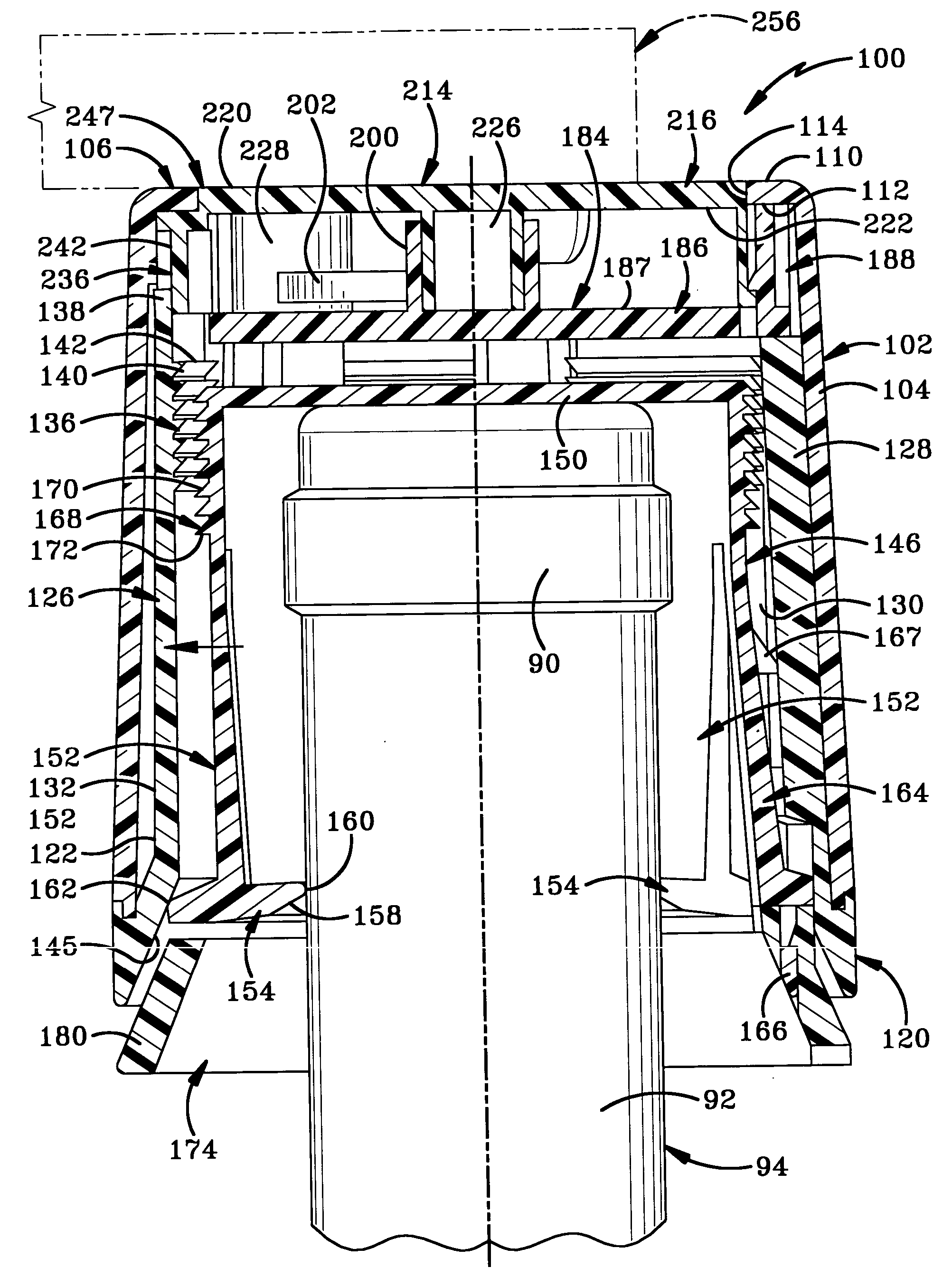
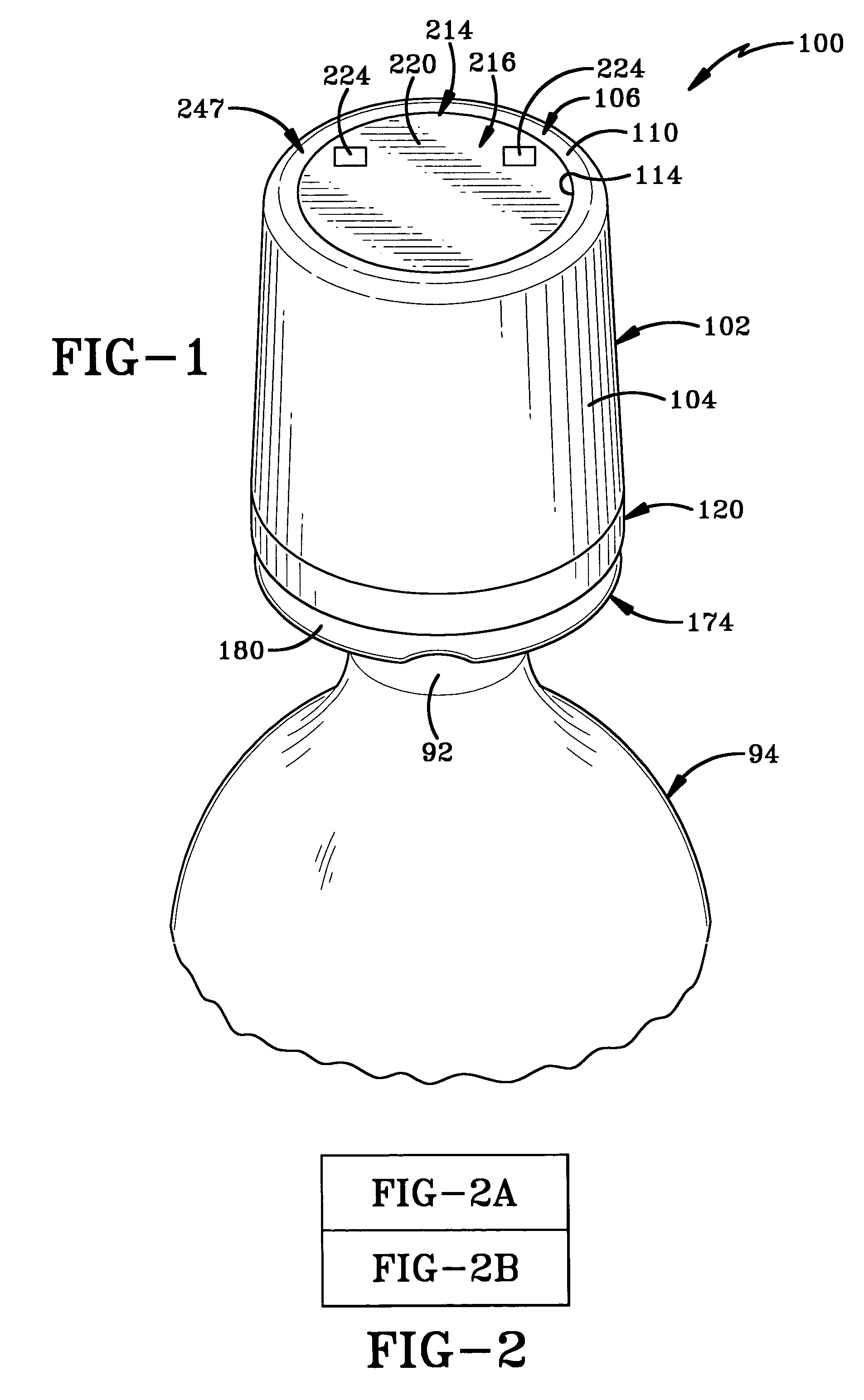
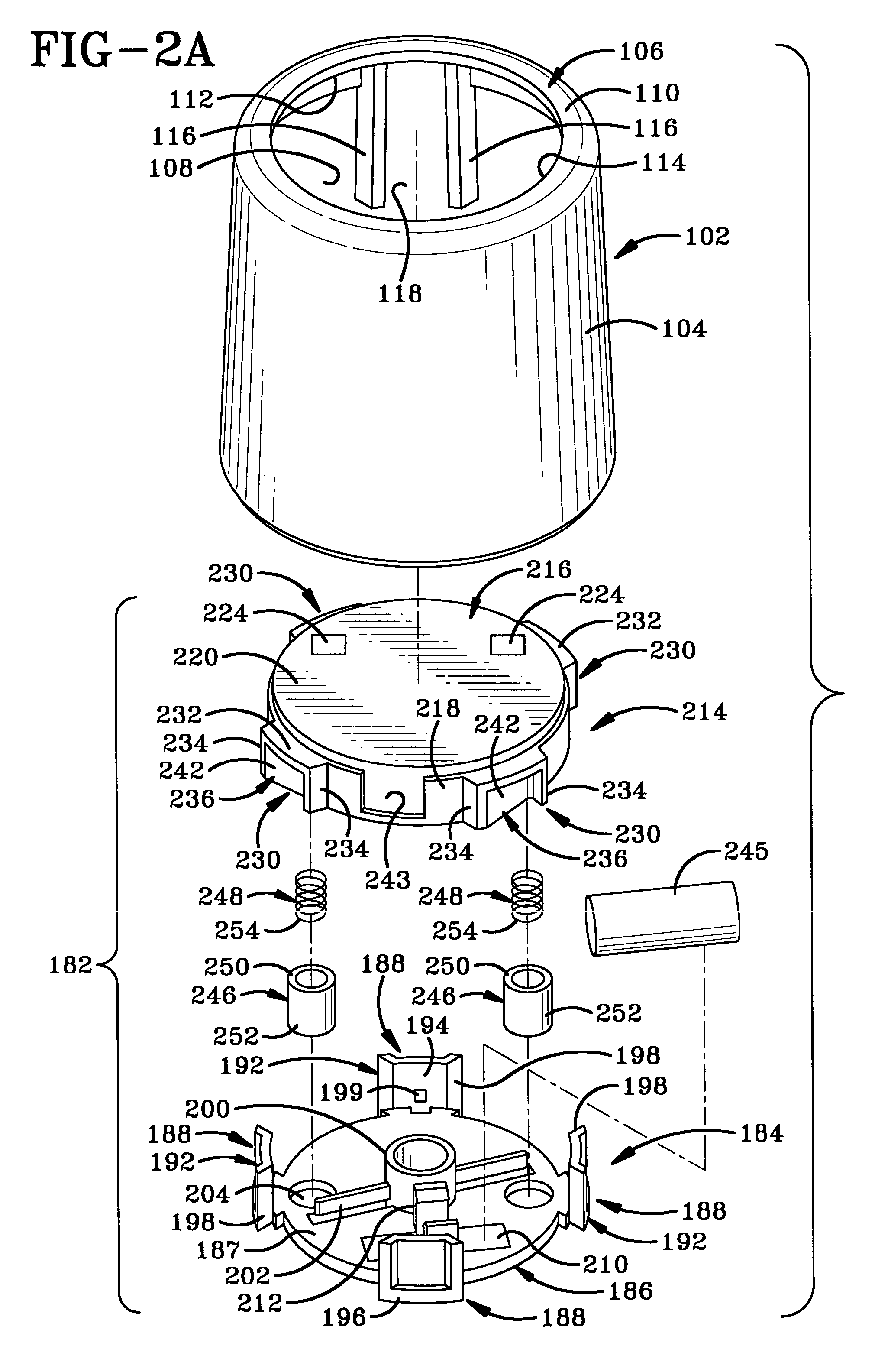
[0036] A bottle security device is indicated generally at 100 and is shown in FIGS. 1-19. Bottle security device 100 generally includes an outer member 102, an intermediate member 120, an inner member 146, and a cover assembly 182 including a cover base 184 and a cover cap 214. Device 100 may also include a lower ring member 174. Device 100 includes a locking mechanism that cooperates to lock device 100 on the neck 92 of a typical bottle 94 and an unlocking mechanism that releases the locking mechanism so that device 100 may be unlocked and removed from bottle neck 92. In the exemplary embodiment, the unlocking mechanism may be locked in a locked position with pistons 246 that move between an extended locked position and a retracted unlocked position. Pistons 246 are biased by springs 248 into the locked position and pulled by a magnetic key 256 into the unlocked position. In an alternative embodiment, the unlocking mechanism may be mechanically actuated, such as the locking mechani...


PUM


Abstract

A bottle security device includes an inner member, an intermediate member and an outer member that cooperate to lock the device on a bottle neck. The inner member includes a plurality of fingers adapted to fit under the bead on a bottle neck. The intermediate member slides over the inner member and forces the fingers against the bottle. The intermediate member includes a plurality of upwardly extending arms with inwardly projecting teeth that engage outwardly extending teeth on the inner member to lock the inner and intermediate members together. A key unlocks and rotates a rotatable member to separate the intermediate and inner members to unlock the device. Upon rotation of the cover cap, camming surfaces on the rotatable member engage the upwardly extending arms to move them radially outward to disengage them from the inner member.

Description


Claims


Application Information

Patent Timeline
Owner CHECKPOINT SYST INC
Features
  • Generate Ideas
  • Intellectual Property
  • Life Sciences
  • Materials
  • Tech Scout
  • Unparalleled Data Quality
  • Higher Quality Content
  • 60% Fewer Hallucinations
Learn More