Spout assemblies for bottles

a technology for spouts and bottles, applied in the field of spout assemblies, can solve problems such as misplacemen

Inactive Publication Date: 2000-02-22
RIGEL DORON
View PDF5 Cites 37 Cited by
  • Summary
  • Abstract
  • Description
  • Claims
  • Application Information

AI Technical Summary

Benefits of technology

An object of the present invention is to provide a spout assembly which do

Problems solved by technology

This is inconvenient, since it requires extra manipulations in removing the spout to apply the cap, and in reapplying the spout

Method used


Image

  • Spout assemblies for bottles
  • Spout assemblies for bottles
  • Spout assemblies for bottles

Examples


Embodiment Construction

With reference first to FIGS. 5 and 6, there is illustrated a bottle, generally designated 2, formed with a neck 4 which is adpated to be closed by a cap 6 (FIG. 6). A spout assembly constructed in accordance with the present invention, and generally designated 8 in FIGS. 5 and 6, is fixedly received within neck 4 of the bottle 2, so that it does not have to be removed in order to apply the cap 6. Thus, when cap 6 is applied, the spout within the assembly 8 is automatically moved to a retracted position, as shown in FIG. 6; and when the cap is removed, the spout automatically moves to an extended position, as shown in FIG. 5, to enable it to be used for pouring out the bottle contents.

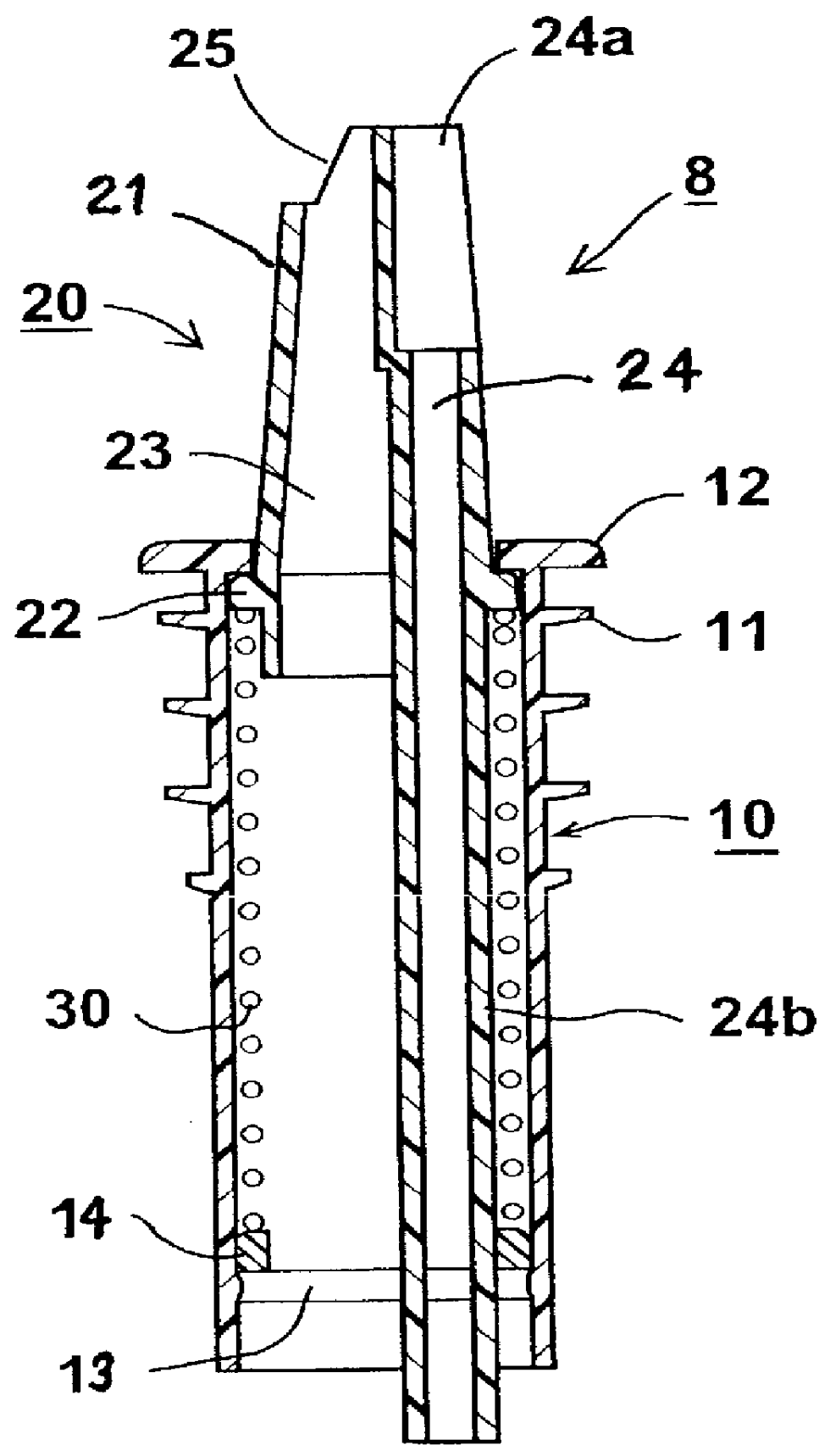
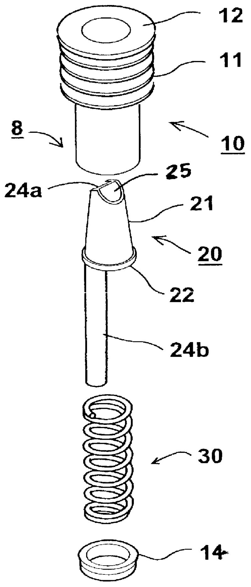
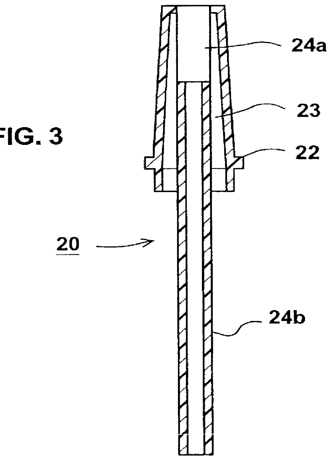
As shown particularly in FIGS. 1 and 2, spout assembly 8 includes a cylindrical sleeve, generally designated 10, fixedly receivable within the bottle neck 4; a spout, generally designated 20, extending through the sleeve and movable therein to an extended position projecting outwardly of the bottle nec...


PUM


Abstract

A sleeve fixedly receivable within the bottle neck, and a spout extending through the sleeve and movable therein to an extended position projecting outwardly of the bottle neck to facilitate pouring contents from the bottle or to a retracted position disposed within the neck when closed by the bottle cap.

Description

FIELD AND BACKGROUND OF THE INVENTIONThe present invention relates to a spout assembly for a bottle, and particularly to a spout assembly for bottles which may be capped without removing the spout assembly.Many different types of bottles are provided with pouring spouts to facilitate pouring the bottle contents out of the bottle. The bottle contents may be a liquid, e.g., an alcoholic drink, but may also be pourable granular material, e.g., salt, flour or the like. Where the bottle is provided with a cap, it is generally necessary to remove the spout before the cap can be applied. This is inconvenient, since it requires extra manipulations in removing the spout to apply the cap, and in reapplying the spout after the cap has been removed. Moreover, the removed spout requires a suitable place for holding it until again needed. Further, removing the spout may also result in its misplacement when the spout is again needed.OBJECTS AND BRIEF SUMMARY OF THE INVENTIONAn object of the presen...

Claims


Application Information

Patent Timeline
IPC IPC(8): B65D47/06
CPCB65D47/061
Inventor RIGEL, DORON
Owner RIGEL DORON
Why Eureka
Try Eureka