
Induction Motor with Ratchet Device

a technology of ratchet and induction motor, which is applied in the direction of dynamo-electric machines, instruments, master clocks, etc., can solve the problems of inability to reduce the manufacturing cost of the motor and low output efficiency

Inactive Publication Date: 2006-11-30
JAPAN SERVO CO LTD
View PDF8 Cites 1 Cited by
  • Summary
  • Abstract
  • Description
  • Claims
  • Application Information

AI Technical Summary

Benefits of technology

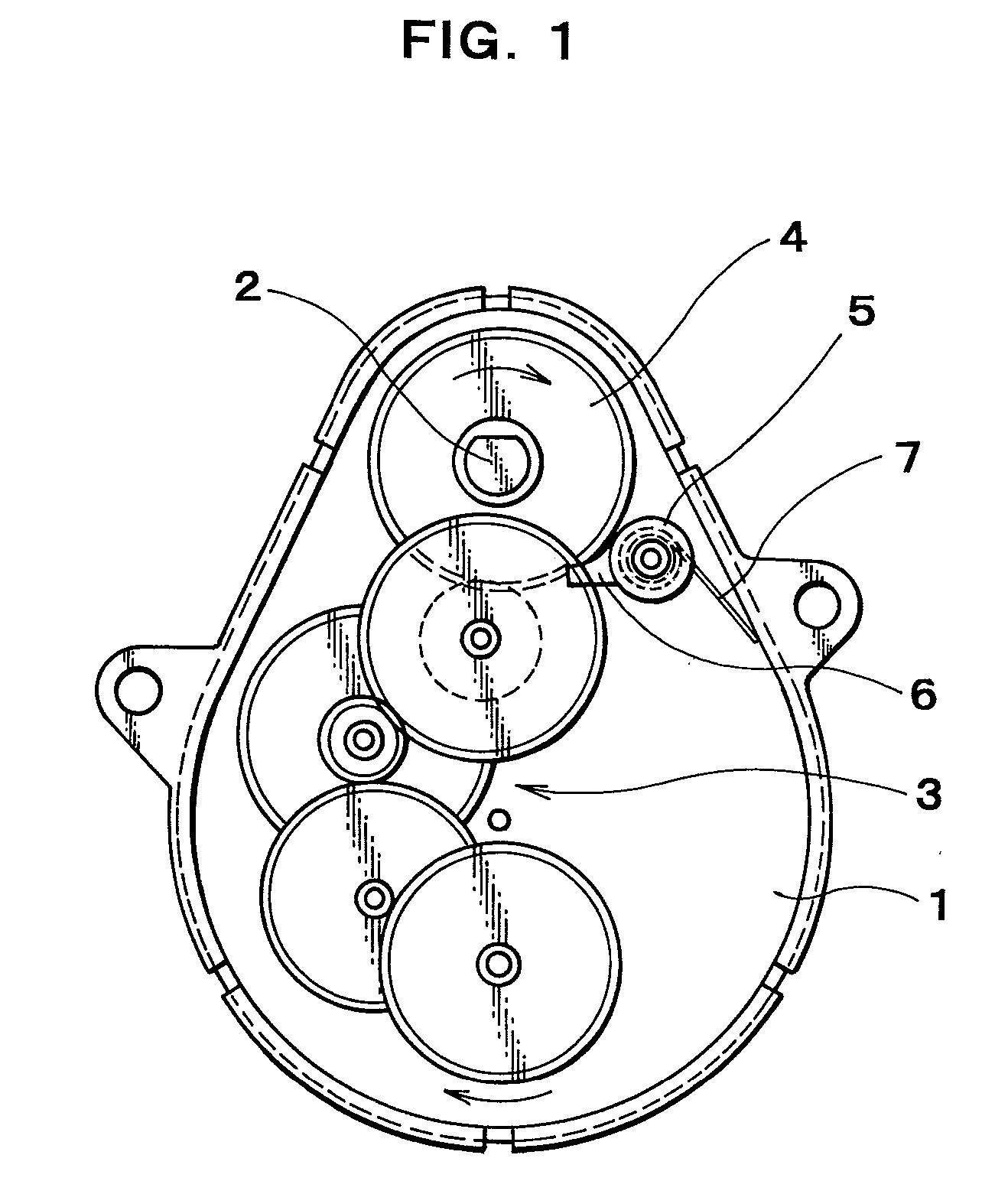
[0009] Another object of the present invention is to provide an induction motor with a ratchet device comprising an induction motor, a gear connected to an output shaft of the motor, a ratchet wheel having a claw for preventing the reverse rotation of the gear, and an urging device for urging the ratchet wheel so that an end surface of a tip end of the claw of the ratchet wheel is brought into contact with a tooth face facing a reverse rotary direction of the gear so as to prevent the reverse rotation of the gear.
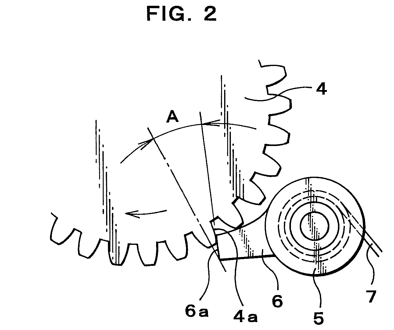
[0011] A further object of the present invention is to provide the induction motor wherein an inside corner of the end surface of the tip end of the claw is projected toward a tooth root of the gear so that the end surface of the tip end of the claw is not removed from the tooth face of the gear when the gear is rotated reversely.

Problems solved by technology

In such hysteresis motor, the output efficiency is very low, and is about 1˜2%, so that the size of the motor cannot be small, and that the manufacturing cost of the motor cannot be reduced.

Method used


Image

  • Induction Motor with Ratchet Device
  • Induction Motor with Ratchet Device
  • Induction Motor with Ratchet Device

Examples


Embodiment Construction

[0016] The present invention will now be explained with reference to the drawings.

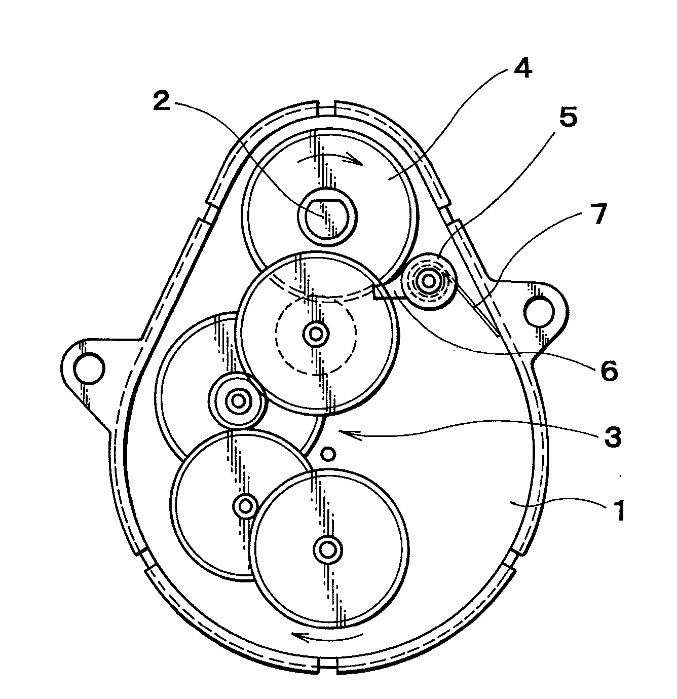
[0017] An induction motor with a ratchet device of the present invention, as shown in FIG. 1 and FIG. 2, comprises a casing 1 contained therein an AC-drive single-phase induction motor (not shown), an output shaft 2 of the motor, gear trains 3 having a gear 4 connected to the output shaft 2, a ratchet wheel 5 having a claw 6, supported rotatably by the casing 1, and a coil spring 7 for urging the ratchet wheel 5 so that an end surface 6a of a tip end of the claw 6 is brought into contact with a tooth face 4a of the gear 4 facing a direction of reverse rotation so as to prevent the reverse rotation of the gear 4.

[0018] In the induction motor with the ratchet device according to the present invention, the forward rotation of the motor can be transmitted through the gear train 3 because the end surface 6a of the tip end of the claw 6 of the ratchet wheel 5 is moved away against the spring action of the ...


PUM


Abstract

An induction motor has a gear connected to an output shaft of the motor, a ratchet wheel having a claw for preventing the reverse rotation of the gear, and an urging device. The urging device urges the ratchet wheel so that an end surface of a tip end of the claw of the ratchet wheel is brought into contact with a tooth face facing a reverse rotary direction of the gear so as to prevent the reverse rotation of the gear. A contact angle formed by the end surface of the tip end of the claw and a center line of the tooth of the end surface of gear preferably is set equal to a pressure angle of the gear.

Description

BACKGROUND OF THE INVENTION [0001] 1. Field of the Invention [0002] The present invention relates to an induction motor with a ratchet device, and more particularly, relates to an induction motor with a ratchet device for use in an automatic ice making apparatus or the like. [0003] 2. Description of the Prior Art [0004] An AC-drive single-phase hysteresis motor is normally used for an automatic ice making apparatus. In such hysteresis motor, the output efficiency is very low, and is about 1˜2%, so that the size of the motor cannot be small, and that the manufacturing cost of the motor cannot be reduced. [0005] An AC-drive single-phase induction motor is also known. Such motor has a high efficiency of about ten times larger than that of the hysteresis motor and accordingly the size and the manufacturing cost thereof can be reduced, however, it is liable to rotate in the reverse direction because of the single-phase motor. [0006] Japanese Patent Application Laid-Open No. 198639 / 91 dis...

Claims


Application Information

Patent Timeline
Patent Type & Authority Applications(United States)
IPC IPC(8): H02K7/06H02K37/14
CPCH02K7/07
Inventor MAEHARA, TOSHIOKURODA, EIJI
Owner JAPAN SERVO CO LTD
Learn More