Alternating hardmasks for tight-pitch line formation

Active Publication Date: 2018-08-30
TESSERA LLC
View PDF1 Cites 0 Cited by
  • Summary
  • Abstract
  • Description
  • Claims
  • Application Information

AI Technical Summary

Benefits of technology

The patent describes methods for making fins on a layer of material using three different hardmasks, which are substances used to create patterns. The first hardmask is used to make fins of a first material, which are then etched away to leave gaps. The second hardmask is then put into the gaps to make fins of a second material. This process creates a tri-color hardmask, which has fins of three different materials arranged in a pattern. The technical effects of this invention include more precise formation of fins and the ability to create complex patterns using multiple hardmasks.

Problems solved by technology

As these devices scale down in size, performance can be increased but fabrication becomes more difficult.
In particular, errors in edge placement, critical dimension, and overlay approach the size of the structures being fabricated, making it difficult to accurately form such structures.
One particular challenge in forming fin structures is the selective removal of particular fins.
For example, while a series of fins can be created using, e.g., sidewall image transfer techniques, significant errors in masking the fins may occur when operating near the limit of the lithographic process.
Such errors may cause fins neighboring the removed fin to be damaged or removed entirely.

Method used


Image

  • Alternating hardmasks for tight-pitch line formation
  • Alternating hardmasks for tight-pitch line formation
  • Alternating hardmasks for tight-pitch line formation

Examples


Embodiment Construction

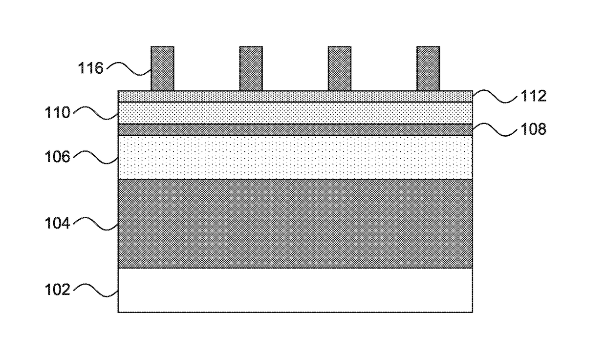
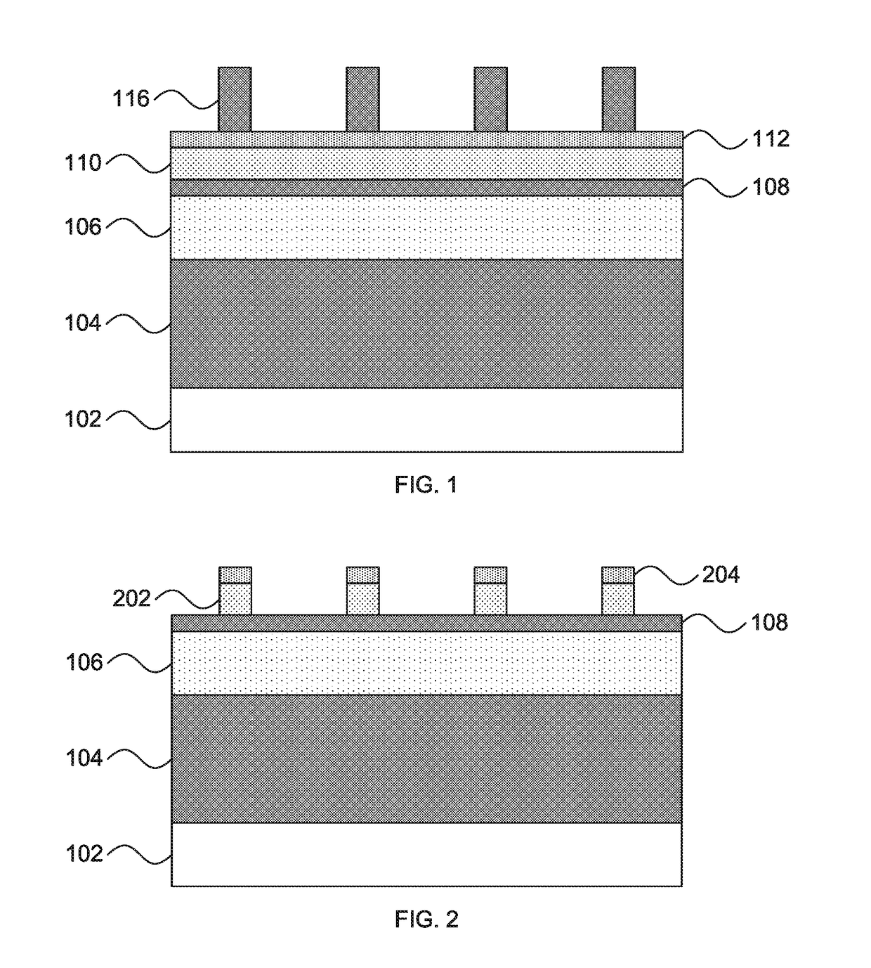
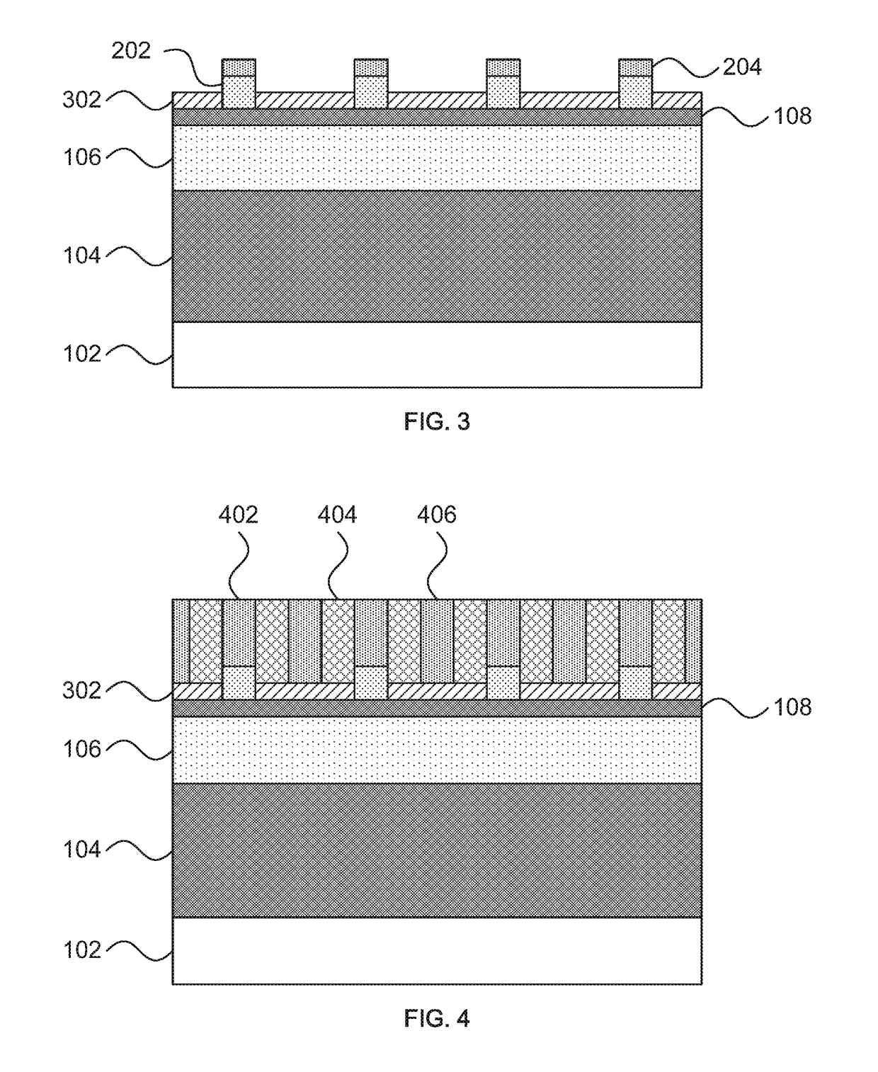
[0027]Embodiments of the present invention provide a hardmask fabrication process that may be used for fin formation in semiconductor fabrication. The present embodiment forms hardmask fins of three different compositions that have mutual etch selectivity, such that a spacing between fins of the same type is large enough that lithographic masking errors will not interfere when selectively removing fins. This provides a tri-color alternating hardmask, where the three different “colors” represent the three different fin hardmask composition. Thus the term “color” is defined herein to refer to one particular hardmask composition.

[0028]The present disclosure therefore refers to “first-color,”“second-color,” and “third-color” materials and fins. Each of these “colors” can be etched selectively to the other two, making it possible to remove a fin of one color without damaging nearby fins of a different color.

[0029]Referring now to FIG. 1, a cross-sectional diagram of a step in forming tri...


PUM


Abstract

A method for forming fins includes forming a three-color hardmask fin pattern on a fin base layer. The three-color hardmask fin pattern has hardmask fins of three mutually selectively etchable compositions. A region on the three-color hardmask fin pattern is masked, leaving one or more fins of a first color exposed. All exposed fins of the first color are etched away with a selective etch that does not remove fins of a second color or a third color. The mask and all fins of a second color are etched away. Fins are etched into the fin base layer by anisotropically etching around remaining fins of the first color and fins of the third color.

Description

BACKGROUNDTechnical Field[0001]The present invention generally relates to semiconductor fabrication and, more particularly, to the formation of hardmasks in semiconductor fabrication processes.Description of the Related Art[0002]Fin field effect transistors (FinFETs) and other fin-based devices are frequently used in semiconductor structures to provide small-scale integrated circuit components. As these devices scale down in size, performance can be increased but fabrication becomes more difficult. In particular, errors in edge placement, critical dimension, and overlay approach the size of the structures being fabricated, making it difficult to accurately form such structures.[0003]One particular challenge in forming fin structures is the selective removal of particular fins. For example, while a series of fins can be created using, e.g., sidewall image transfer techniques, significant errors in masking the fins may occur when operating near the limit of the lithographic process. S...

Claims


Application Information

Patent Timeline
IPC IPC(8): H01L21/308H01L21/3065H01L29/66
CPCH01L21/3088H01L21/3065H01L29/66795H01L21/3085H01L21/3086H01L21/3081H01L21/823431H01L21/0337
Inventor BURNS, SEAN D.FELIX, NELSON M.LIU, CHI-CHUNMIGNOT, YANN A.M.SIEG, STUART A.
Owner TESSERA LLC
Why Eureka
Try Eureka