
Multiple substrate microelectronic devices and methods of manufacture

Inactive Publication Date: 2005-01-27
ROUND ROCK RES LLC
View PDF85 Cites 3 Cited by
  • Summary
  • Abstract
  • Description
  • Claims
  • Application Information

AI Technical Summary

Benefits of technology

[0006] In a further aspect of the invention, the method can further include selecting the first and second microelectronic substrates to include microelectronic dies separated from one or more microelectro

Problems solved by technology

One drawback with this arrangement is that the circuit board may have a large surface area to accommodate a large number of microelectronic devices.
Accordingly, it may be difficult to fit the circuit board into a housing of a compact electronic product.
However, the adhesive can have several drawbacks.
Another drawback is that the adhesive attached.
In some cases, these stresses can crack or fracture the dies.

Method used


Image

  • Multiple substrate microelectronic devices and methods of manufacture
  • Multiple substrate microelectronic devices and methods of manufacture
  • Multiple substrate microelectronic devices and methods of manufacture

Examples


Embodiment Construction

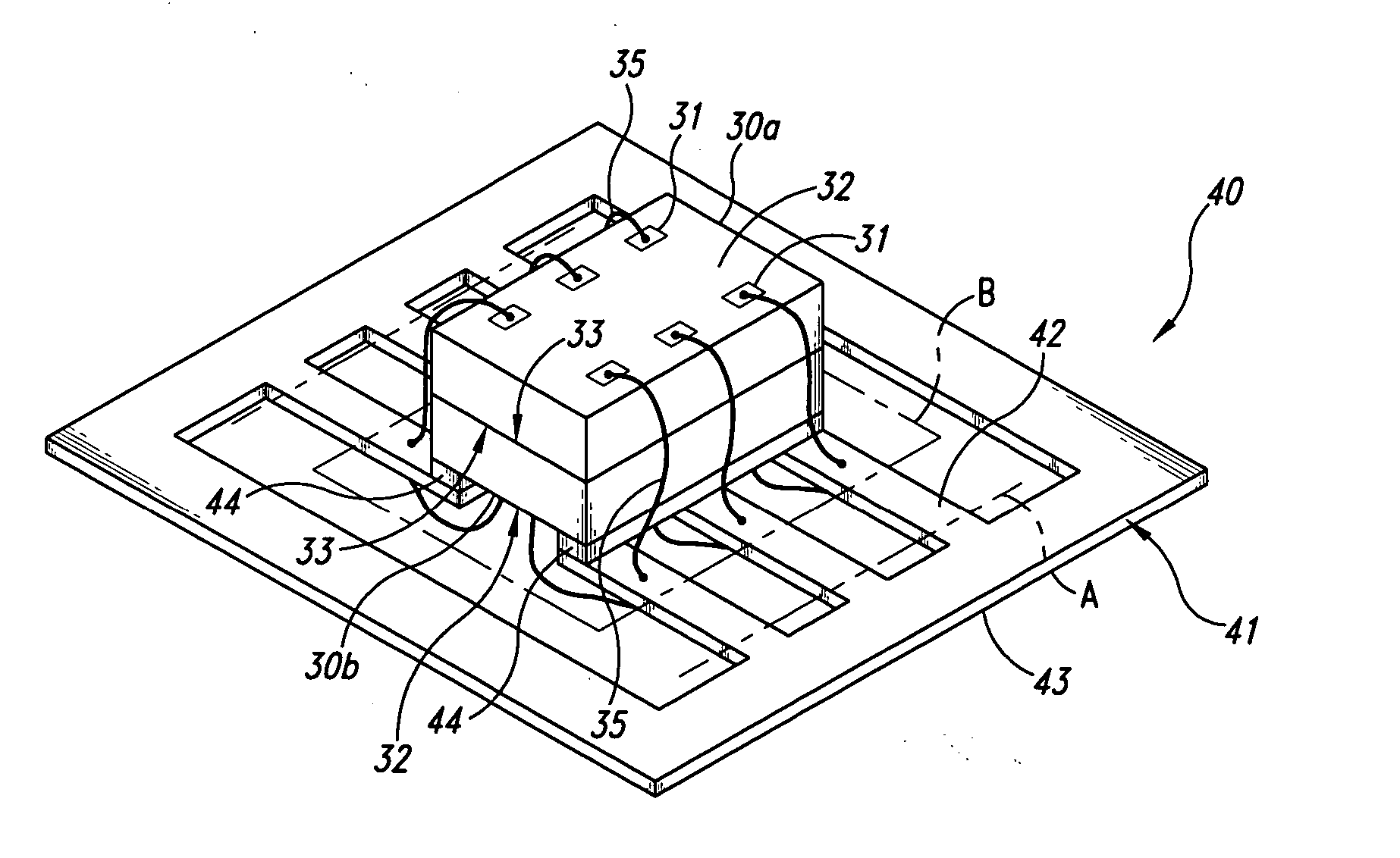
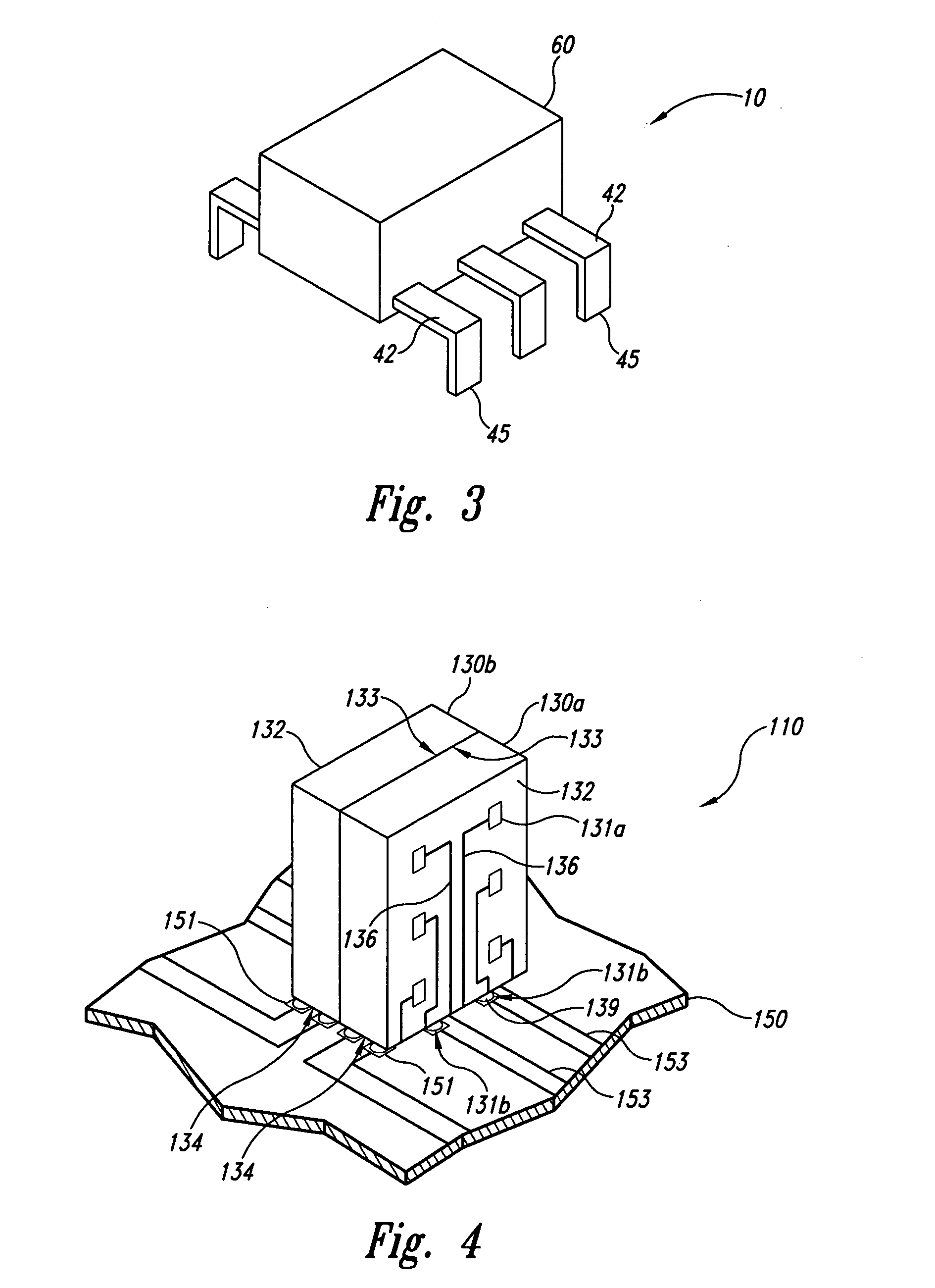
[0017] The present disclosure describes microelectronic devices and methods for forming such devices. Many specific details of certain embodiments of the invention are set forth in the following description and in FIGS. 1-7 to provide a thorough understanding of these embodiments. One skilled in the art, however, will understand that the present invention may have additional embodiments, or that the invention may be practiced without several of the details described below.

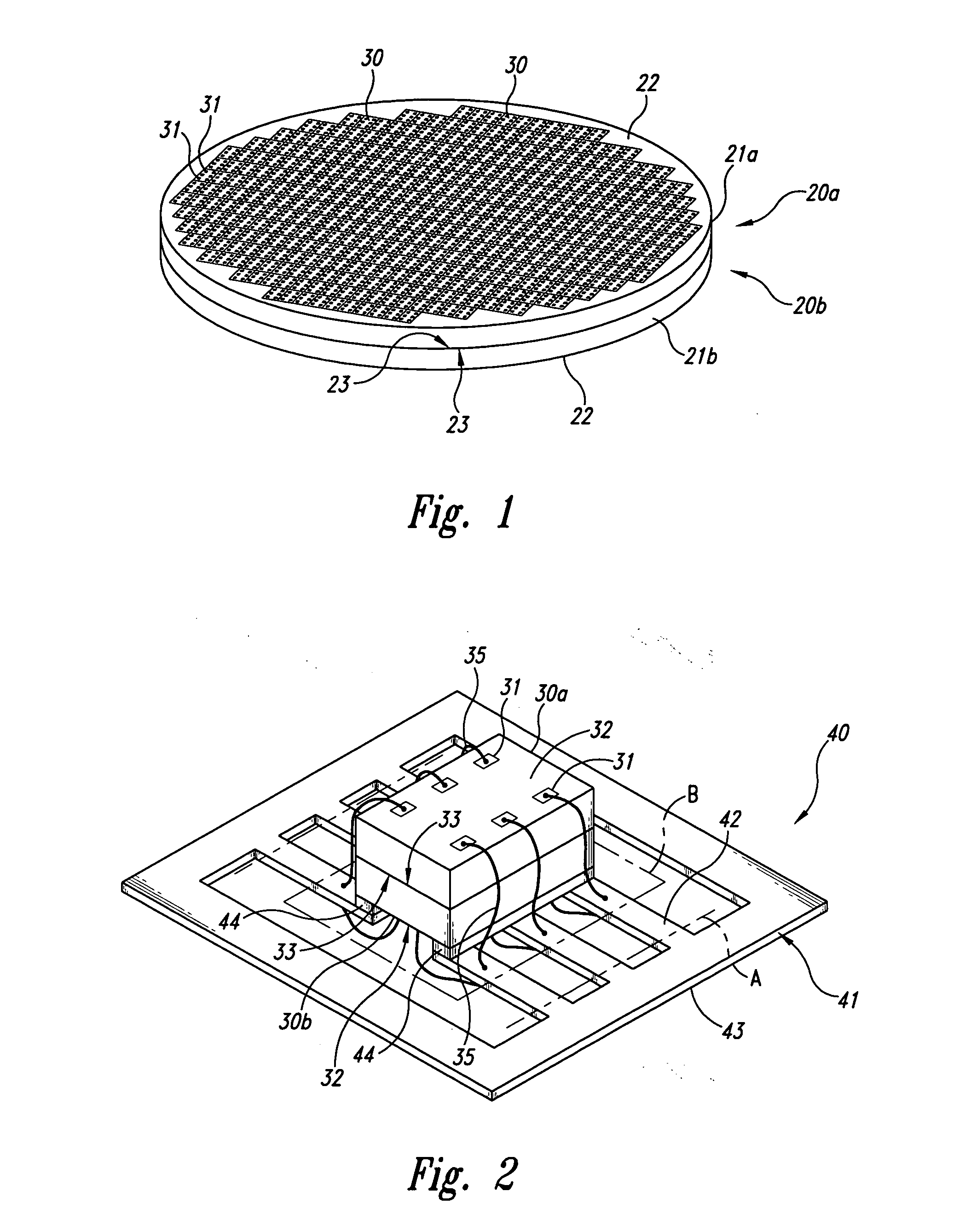
[0018]FIG. 1 is a top isometric view of a first microelectronic substrate 20a bonded to a second microelectronic substrate 20b (referred to collectively as “microelectronic substrates 20”) in accordance with one embodiment of the invention. In one aspect of this embodiment, the first microelectronic substrate 20a includes a first wafer 21a and the second microelectronic substrate 20b includes a second wafer 21b (referred to collectively as “wafers 21”). The wafers 21 can include silicon or another suitable substra...


PUM


Abstract

A microelectronic device and method for manufacture. In one embodiment, two microelectronic substrates are directly bonded to each other without an intermediate adhesive material. For example, each microelectronic substrate can include a first surface, a second surface opposite the first surface, and a functional microelectronic feature coupled to a connection terminal of the microelectronic substrate. The connection terminals can be coupled to a support member, such as a leadframe or a printed circuit board, with the bond plane between the microelectronic substrates either aligned with or transverse to the support member. The microelectronic substrates can be enclosed in a protective packaging material that can include a transparent window to allow selected radiation to strike one or the other of the microelectronic substrates.

Description

TECHNICAL FIELD [0001] This invention relates to microelectronic devices having multiple substrates and methods for manufacturing such microelectronic devices. BACKGROUND OF THE INVENTION [0002] Microelectronic devices, such as memory chips and microprocessor chips, typically include a microelectronic substrate die encased in a plastic, ceramic or metal protective covering. The die includes functional features, such as memory cells, processor circuits, and interconnecting circuitry. The die also typically includes bond pads electrically coupled to the functional features. The bond pads are coupled to terminals, such as pins, that extend outside the protective covering for connecting to buses, circuits and / or other microelectronic devices. [0003] Conventional microelectronic devices are typically arranged side-by-side on a circuit board or other support device that is incorporated into a computer, mobile phone or other larger electronic product. One drawback with this arrangement is ...

Claims


Application Information

Patent Timeline
IPC IPC(8): H01L23/495H01L25/065
CPCH01L23/49575H01L24/16H01L24/29H01L24/33H01L24/48H01L24/49H01L24/83H01L24/94H01L25/0657H01L25/50H01L2224/05553H01L2224/13099H01L2224/16H01L2224/32014H01L2224/32145H01L2224/48091H01L2224/48145H01L2224/48227H01L2224/48247H01L2224/4826H01L2224/48464H01L2224/49175H01L2224/83894H01L2225/06506H01L2225/0651H01L2225/06517H01L2225/06555H01L2924/01005H01L2924/01014H01L2924/01082H01L2924/078H01L2224/2919H01L2224/32245H01L2224/73215H01L2224/73265H01L2924/014H01L2924/0665H01L2224/16225H01L2224/32225H01L2224/0401H01L2924/00014H01L2924/00H01L2924/3512H01L2924/00012H01L24/73H01L2924/10161H01L2224/023H01L2224/45099H01L2224/05599H01L2924/0001
Inventor JIANG, TONGBIBROOKS, J. MICHAEL
Owner ROUND ROCK RES LLC
Learn More