
Method and apparatus for connecting multiple coaxial cables to a printed circuit board in a compact

a technology of printed circuit board and coaxial cable, which is applied in the direction of insulating conductor/cable, fixed connection, coupling device connection, etc., to achieve the effect of convenient disassembly and reassembling

Inactive Publication Date: 2005-01-27
GE MEDICAL SYST GLOBAL TECH CO LLC
View PDF9 Cites 11 Cited by
  • Summary
  • Abstract
  • Description
  • Claims
  • Application Information

AI Technical Summary

Benefits of technology

"The present invention provides a method and apparatus for connecting multiple coaxial cables to a printed circuit board without the need for an additional connector element. The cables are bonded to a flexible carrier using alignment pins and a first rigid element and a second rigid element are pressed together to achieve contact between the flexible carrier and the printed circuit board. An elastic element can also be used to provide a predictable contact force. The shields of the cables can be connected together by soldering them to a conductive area of the flexible carrier. The technical effects of this invention include easy disassembly and reassembly, compact location, and no requirement for cement or other bonding media."

Problems solved by technology

However, and despite this additional functionality, the carrier to which the coaxes are bound is very small so that it does not add significantly to the size of the overall bundle of coaxes.

Method used


Image

  • Method and apparatus for connecting multiple coaxial cables to a printed circuit board in a compact
  • Method and apparatus for connecting multiple coaxial cables to a printed circuit board in a compact
  • Method and apparatus for connecting multiple coaxial cables to a printed circuit board in a compact

Examples


Embodiment Construction

The following detailed description is intended to describe the preferred embodiments that are depicted in the various figures referred to above. It is to be understood, however, that changes could be made to that which is specifically described and shown that would still fall within the scope of the present invention.

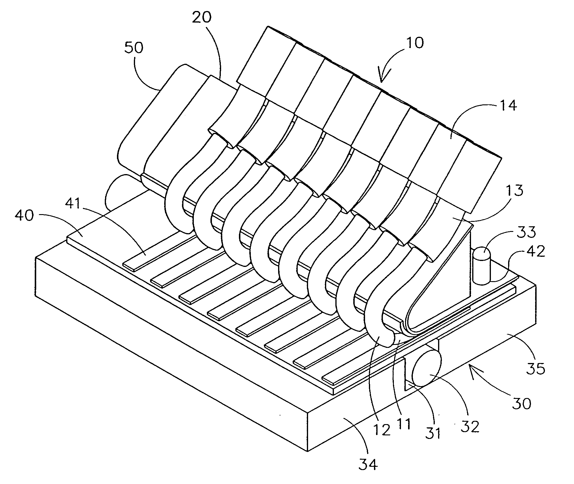
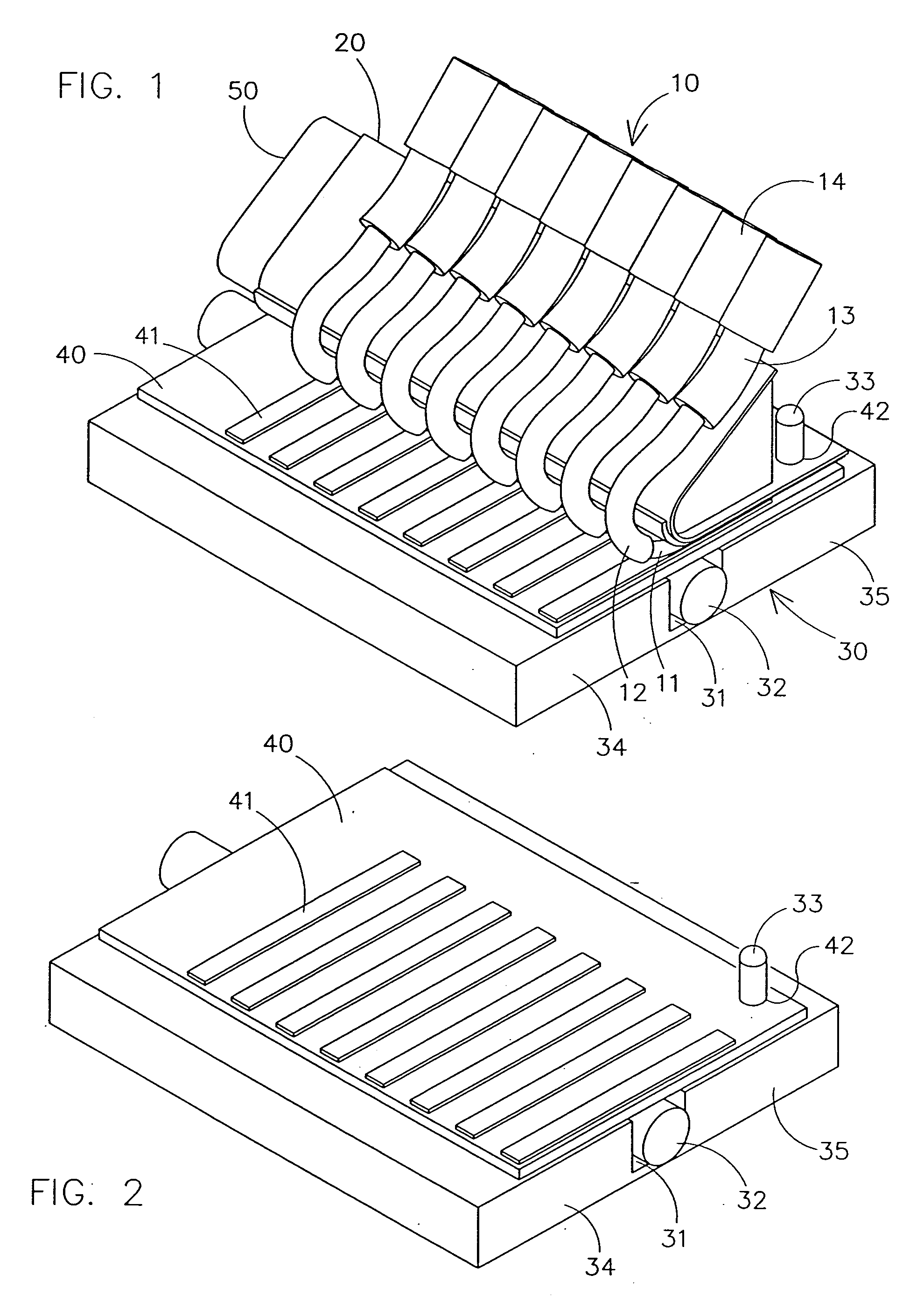
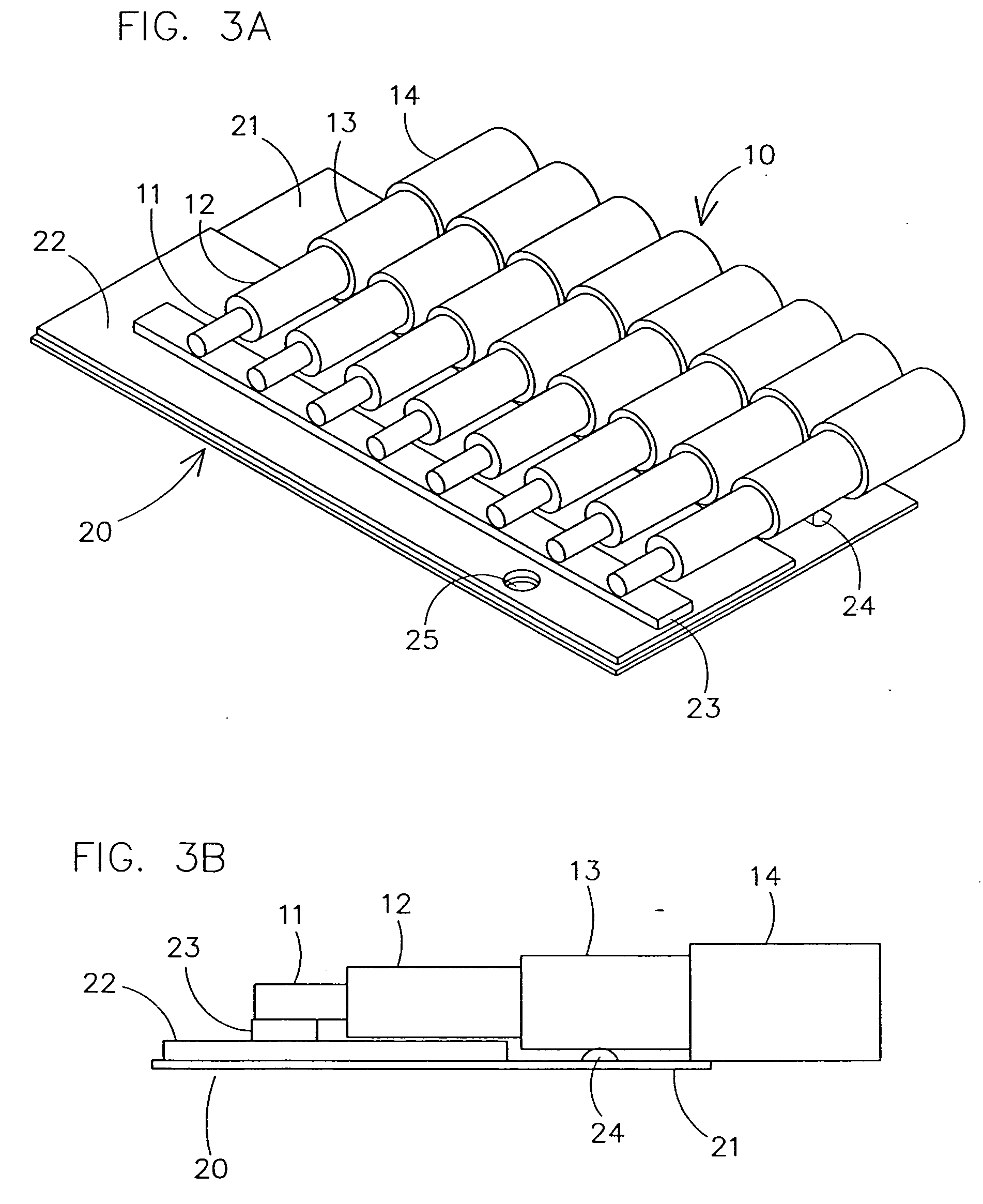
Referring now to the drawings in detail, wherein like numbered elements refer to like elements throughout, FIG. 1 illustrates a preferred embodiment of the apparatus employed in conjunction with the method of the present invention. As can be seen from FIG. 1, the apparatus and method of the present invention provides for a complete connection package. What is not seen is that the connection is very small. Also, the method and apparatus of the present invention is utilized with an array of parallel coaxial cables, generally identified 10, each of which is already present in the device for which this invention is intended. A base plate 30 is also typically an existing ...


PUM

PropertyMeasurementUnit
internal diameteraaaaaaaaaa
distanceaaaaaaaaaa
flexibleaaaaaaaaaa

Abstract

A method and apparatus for connecting a plurality of coaxial cables to a printed circuit board in a compact connector. The apparatus is generally comprised of a flexible carrier, means for attaching the cable to the flexible carrier, a conductive base plate and a rigid beam providing pressure such that the electrical contact between the coaxial cable and the printed circuit board is maintained. The method generally comprises the steps of stripping the coaxial cables, bonding the coaxial cable to a flexible carrier, positioning the coaxial cables over traces of a printed circuit board providing pressure such that electrical contact is maintained between the cables and the printed circuit board.

Description

BACKGROUND OF THE INVENTION This invention relates generally to coaxial cables and to methods and devices for connecting coaxial cables to other elements. More particularly, it relates to a method and apparatus for connecting a plurality of coaxial cables to a printed circuit board, or to a printed wiring board, using a compact connector. There are many situations and applications where it is necessary to connect a multicoaxial cable comprised of a large number of small coaxial elements to the traces of a printed circuit board (PCB) or to a printed wiring board (PWB). Generally, the small coaxial elements need to be attached, detached and reattached from the PCB or PWB rather frequently. When doing so, a large number of the smaller elements must mate up with the PCB or PWB in what is typically a very small location. In the experience of these inventors, the medical field also has a peculiar need for a method and apparatus for connecting multiple coaxial cables to a PCB in a compa...

Claims


Application Information

Patent Timeline
Patent Type & Authority Applications(United States)
IPC IPC(8): H05K7/00H01R9/05H01R12/04H01R12/62H01R43/00H01R43/02H01R43/20H05K3/32
CPCH01R9/0515Y10T29/49222H01R43/0249H01R43/205H05K3/0061H05K3/325H05K2201/09809H05K2201/10356H05K2201/10424H01R12/598Y10T29/5193Y10T29/49149Y10T29/49139Y10T29/49117Y10T29/49174Y10T29/53209Y10T29/49123H01R12/62
Inventor EDWARDSEN, STEPHEN DODGEBRON, ALPHONSE LEONRONANDER, JONJORDFALD, DAG
Owner GE MEDICAL SYST GLOBAL TECH CO LLC
Learn More