Electronic control unit

a control unit and electronic technology, applied in the direction of electrical apparatus casings/cabinets/drawers, electrical apparatus connection connections, casings/cabinets/drawers, etc., can solve the problem of difficulty in maintaining the airtight environment of the electronic control unit, and achieve the effect of maintaining the airtight environmen

Active Publication Date: 2005-01-27
DENSO CORP
View PDF1 Cites 12 Cited by
  • Summary
  • Abstract
  • Description
  • Claims
  • Application Information

AI Technical Summary

Benefits of technology

[0016] Accordingly, it is an object of the present invention to provide an electronic control unit capable of sufficiently maintaining the airtightness thereof.

Problems solved by technology

If the crack occurs in the seal member J4 between the connector J2 and the case J1, it might be difficult to maintain the airtightness environment of the electronic control unit.

Method used


Image

  • Electronic control unit
  • Electronic control unit
  • Electronic control unit

Examples


first embodiment

[0038] (First Embodiment)

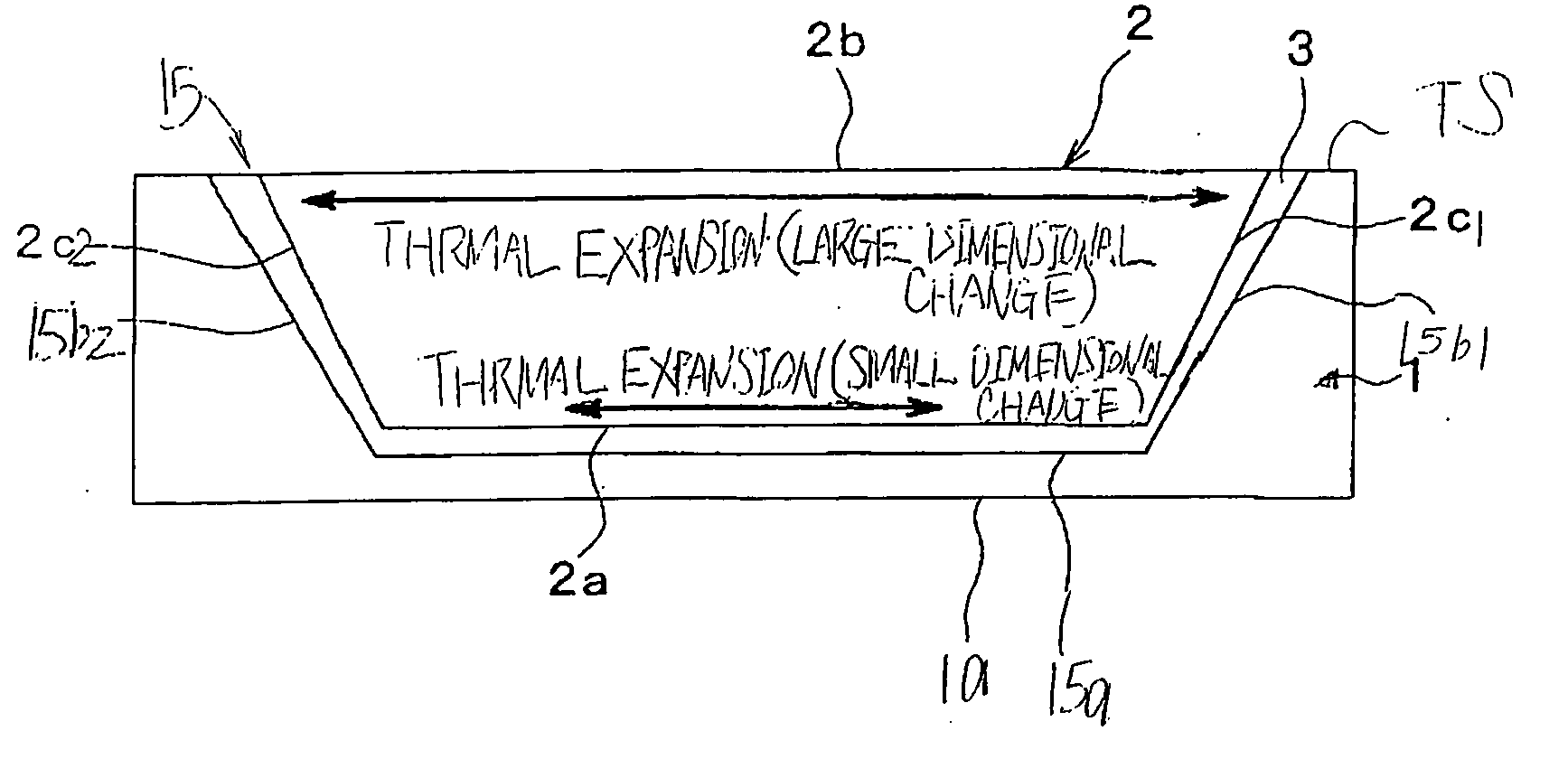
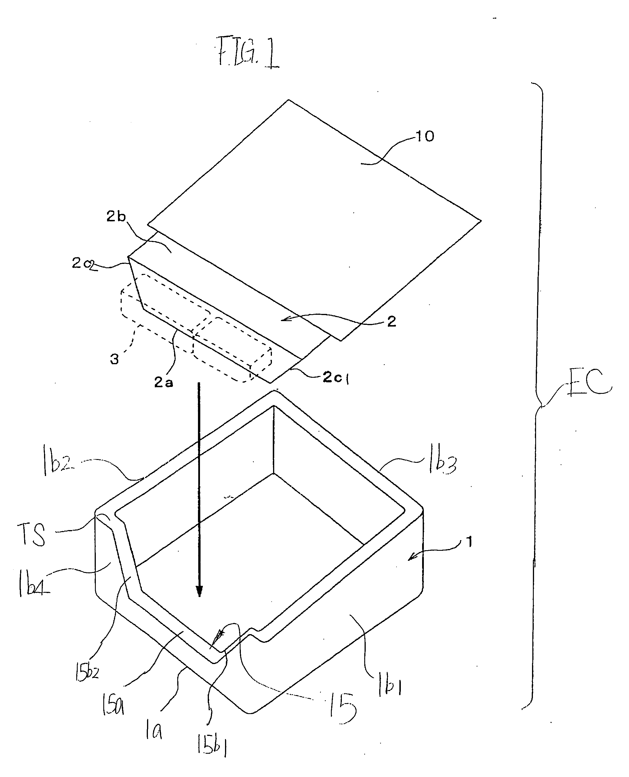
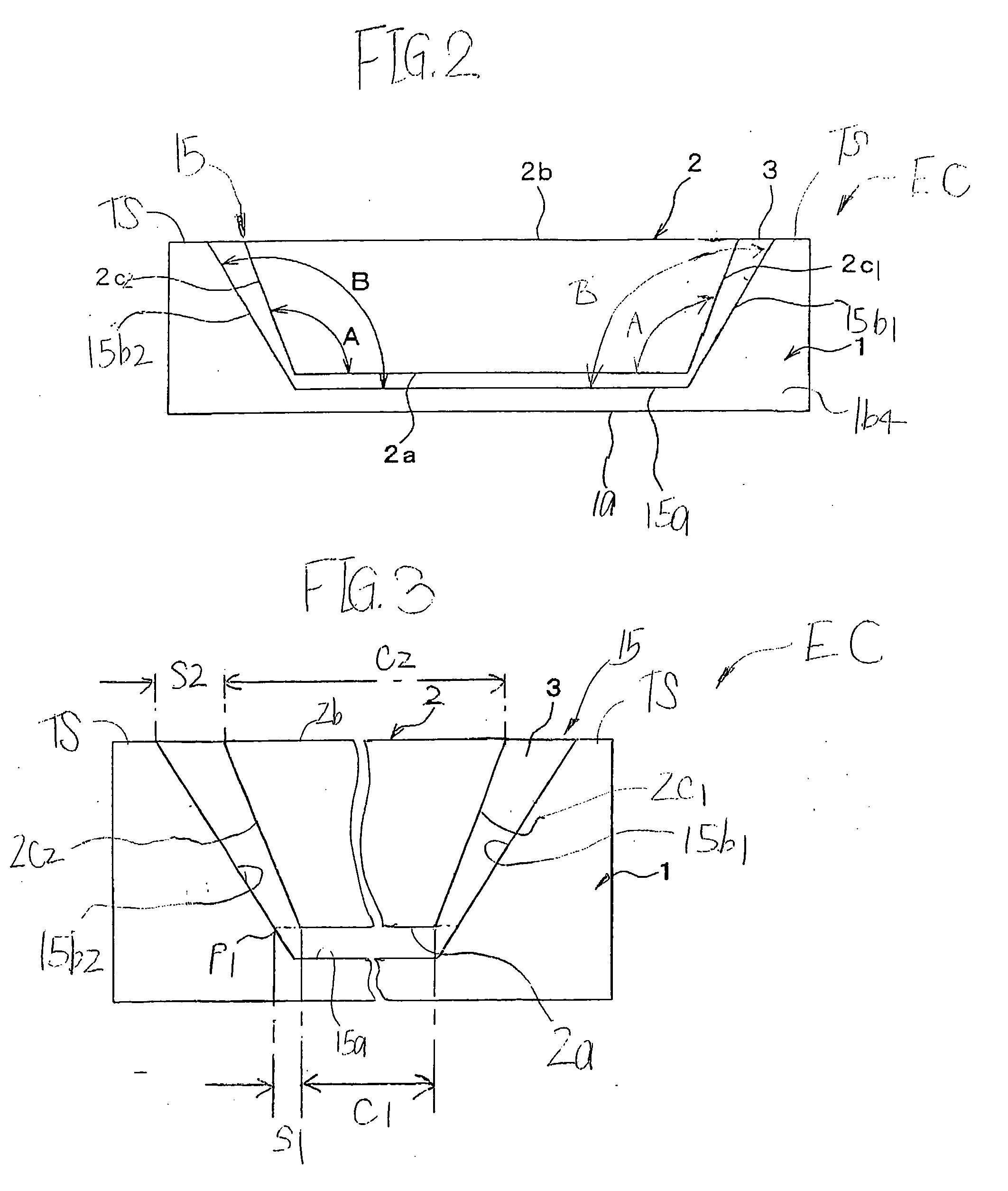
[0039]FIG. 1 is an exploded perspective view of an electronic control unit EC according to a first embodiment of the present invention, which illustrates a state that a connector 2 of the electronic control unit EC is attached to a case 1 thereof. FIG. 2 is a front view of the electronic control unit EC in a state that the connector 2 is completely attached to the case 1.

[0040] The electronic control unit EC according to the first embodiment is applied to an ECU for engines.

[0041] As shown in FIGS. 1 and 2, the case 1 has, for example, a substantially rectangular parallelepiped shape and is made of a material having a first linear expansion coefficient, for example, metal such as aluminum or resin.

[0042] The case 1 has a rectangular bottom wall 1a and a top opened surface opposite thereto. The case 1 also has a pair of longitudinal side walls 1b1 and 1b2 extending upwardly from the two longitudinal sides of the bottom wall 1a, respectively. The case 1 fur...

second embodiment

[0079] (Second Embodiment)

[0080]FIG. 6 is a front view of an electronic control unit EC1 according to a second embodiment of the present invention. In this second embodiment, the electronic control unit EC1 has a connector 2×whose shape is different from the connector 2 according to the first embodiment.

[0081] Other elements of the electronic control unit EC1 are substantially identical with those of the electronic control unit EC according to the first embodiment so that they are assigned to the same reference characteristics of the electronic control unit EC shown in FIG. 1, and explanations thereabout are omitted.

[0082] In this second embodiment, the connector 2×has chamfered portions 2d1 and 2d2 that are formed by chamfering both of the corner portions formed between both of the other lateral ends of the inclined surfaces 2c1, 2c2 and both lateral ends of the longitudinal surface 2b of the connector 2 shown in FIG. 2.

[0083] That is, the chamfered portions 2d1 and 2d2 extend s...

third embodiment

[0088] (Third Embodiment)

[0089]FIG. 7 is a front view of an electronic control unit EC2 according to a third embodiment of the present invention. In this third embodiment, the electronic control unit EC2 has a case 1X whose shape is different from the case 1 according to the first embodiment.

[0090] Other elements of the electronic control unit EC2 are substantially identical with those of the electronic control unit EC1 according to the second embodiment so that they are assigned to the same reference characteristics of the electronic control unit EC1 shown in FIG. 6, and explanations thereabout are omitted.

[0091] In this third embodiment, similar to the first and second embodiments, the case 1X has the bottom wall 1a, and the side walls 1b1-1b4, and the side wall 1b4 is formed with a concave groove 15×having a substantially inverted isosceles trapezoidal shape.

[0092] The concave groove 15X is composed of the lateral surface 15a, and a pair of rectangular inclined surfaces 15b1a ...


PUM


Abstract

In an electronic control unit, a case has a peripheral side portion formed with a concave groove in which a connector is fitted with a clearance portion between the concave groove and the connector. The connector has first inclined portions connecting its lateral surface (one of its base surfaces) and its longitudinal surface (the other of its base surfaces). Each first inclined portion is inclined with respect to the lateral surface at a first angle. The concave groove comprises a base surface opposite to a lateral surface of the connector and second inclined portions opposite to first inclined portions of the connector, respectively. Each second inclined portion is inclined with respect to the base surface at a second angle. The second angle is larger than the first angle. A seal member is disposed in the clearance portion between the connector and the concave groove of the case so that the seal member seals the clearance portion therebetween.

Description

BACKGROUND OF THE INVENTION [0001] The present invention relates to an electronic control unit containing an electronic device and preferably applied to engine control units (ECUs) for engines. [0002] An electronic control unit suitable for use in the ECUs has a printed circuit board where a plurality of electronic devices, such as a microcomputer, are mounted. The electronic control unit also has a case in which the printed circuit board is contained. [0003] A conventional electronic control unit is illustrated in FIG. 12. In FIG. 12, a connector J2 is attached to one side wall J1a of a case J1 for containing the printed circuit board. [0004] That is, the case J1 is formed at its one side wall J1a with a concave groove J3 having a substantially trapezoidal shape. The connector J2 is fixedly fitted in the concave groove J2 through a seal member J4. The seal member J4 is disposed between an outer peripheral portion of the connector J2 and an inner peripheral portion of the concave gr...

Claims


Application Information

Patent Timeline
Patent Type & Authority Applications(United States)
IPC IPC(8): H05K5/02H01R13/52H01R13/533H05K5/00H05K5/06
CPCH01R13/5202H05K5/069H05K5/061H05K5/0069H05K5/0052
Inventor MIZUTANI, AKIHIRO
Owner DENSO CORP
Why Eureka
Try Eureka