
Controller for remote control system

a remote control and control panel technology, applied in the field of controllers and switches, can solve the problems of difficult to duplicate compared with conventional mechanical keys, door is not unlocked, and engine starting is not enabled

Active Publication Date: 2005-01-27
KK TOKAI RIKA DENKI SEISAKUSHO +1
View PDF4 Cites 38 Cited by
  • Summary
  • Abstract
  • Description
  • Claims
  • Application Information

AI Technical Summary

Benefits of technology

[0011] One aspect of the present invention is a controller for communication with a portable device and connection to an activated apparatus and to an operation unit operable by a user to activate the activated apparatus. The controller includes a control unit for transmitting a request signal to a first area and a drive radio wave to a second area. The portable device transmits an ID code in response to the request signal or the drive radio wave, and the control unit enables activation of the activated apparatus when the ID code transmitted from the portable device matches an ID code of the controller. The control unit transmits the drive radio wave in a state in which the activation of the activated apparatus is not enabled after the request signal is transmitted when the operation unit undergoes an operation performed by the user.

Problems solved by technology

In addition, the door is not unlocked and the starting of the engine is not enabled unless the driver is carrying the portable device, which is extremely difficult to duplicate compared with a conventional mechanical key.
When the battery is drained, communication cannot be performed between the portable device and the controller of the automobile.
This invalidates the smart function.
In this structure, the arrangement of a key cylinder or a slot for receiving the immobilizer key increases cost and occupies space.
However, the driver cannot use the immobilizer function without a trigger for switching the smart function to the immobilizer function.
Further, the switch may detect objects other than the portable device.
Thus, in a state in which communication between the portable device and the controller is possible, when the communication control is switched from normal control to backup control even though the driver does not intend to do so, the driver may not be able to start the engine using the smart ignition function.
In such a case, the engine cannot be started since the necessary verification cannot be performed through communication between the portable device and the engine controller.
This may mislead the driver into believing that the engine control system is not functioning properly.

Method used


Image

  • Controller for remote control system
  • Controller for remote control system
  • Controller for remote control system

Examples


first embodiment

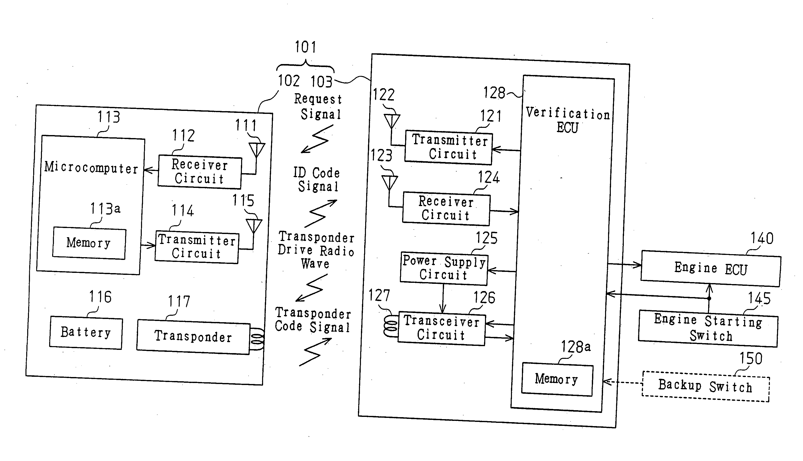
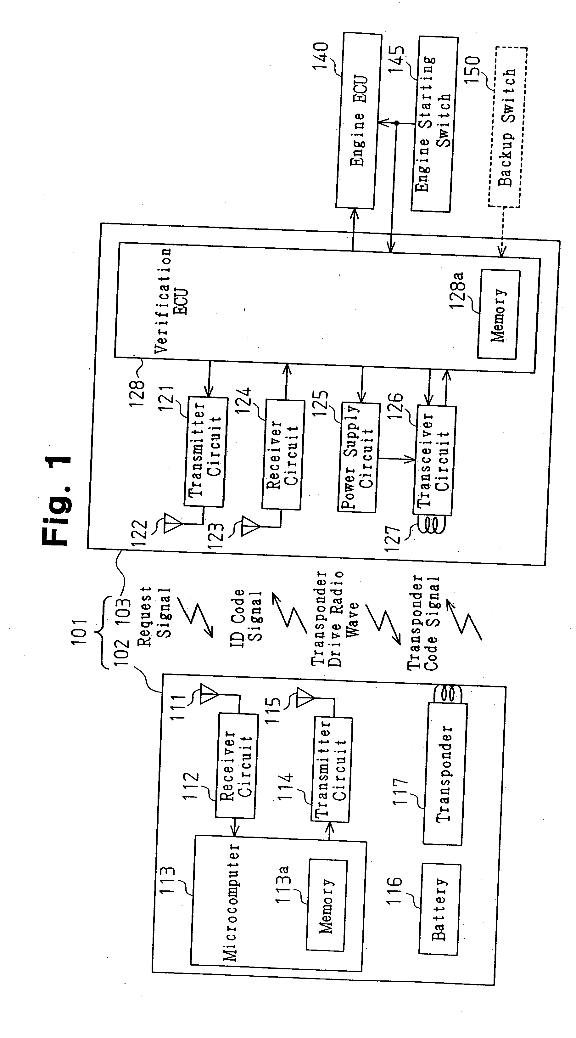
[0035] A controller 103 of a remote control system 101 according to the present invention will now be described.

[0036] Referring to FIG. 1, a remote control system 101 includes a portable device 102 and a controller 103. The portable device 102 transmits an ID code signal including an ID code and a transponder code signal including a transponder code. The controller 103 transmits a request signal and a transponder drive radio wave.

[0037] The portable device 102, which is carried by a driver (user), includes a receiver antenna 111, a receiver circuit 112, a microcomputer 113, a transmitter circuit 114, a transmitter antenna 115, a battery 116, and a transponder 117. The receiver circuit 112 receives a request signal from the controller 103 via a receiver antenna 111, demodulates the request signal to generate a received signal, and provides the received signal to the microcomputer 113. The microcomputer 113 includes a CPU, a ROM, and a RAM (none shown) in addition to a memory 113a. ...

second embodiment

[0064] A controller 203 and an engine starting switch 240 of a remote control system 201 according to the present invention will now be discussed.

[0065] Referring to FIG. 4, the remote control system 201 includes a portable device 202 and the controller 203. The structure of the portable device 202 is the same as the portable device 102 of the first embodiment.

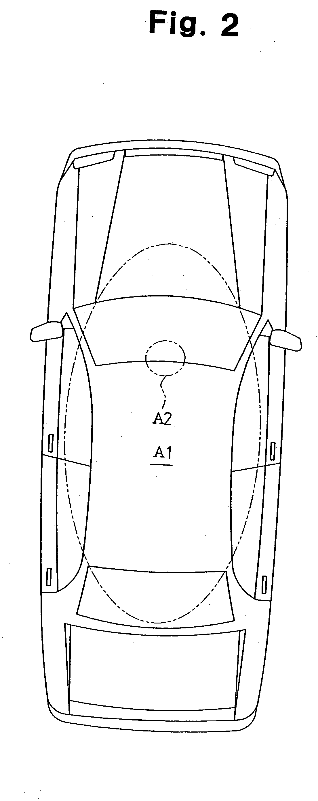
[0066] The controller 203, which is installed in an automobile, includes a power supply circuit 221, a transceiver circuit 222, a transceiver antenna223, a receiver antenna 224, a receiver circuit 225, and a verification ECU 226. The transceiver circuit 222 modulates a request signal, which is provided from the verification ECU 226, to a radio wave having a predetermined frequency (134 KHz in the second embodiment) and transmits the radio wave to a predetermined first area A1 via the transceiver antenna 223. Referring to FIG. 5, the transceiver antenna 223 is located in the middle of an instrument panel. The transceiver circu...

third embodiment

[0088] An engine starting switch 240 according to the present invention will now be described.

[0089] The structures of the portable device and the controller in the third embodiment are the same as the structures of the portable device 202 and the controller 203 in the second embodiment.

[0090] Referring to FIG. 7, the engine starting switch 240 of the third embodiment is a seesaw switch including a button 242 that may be inclined by the driver from a home position Q0 in a first direction or a second direction. When the driver inclines the button 242 in the first direction from the home position Q0, the engine starting switch 240 is moved to an engine starting position Q1. The engine starting switch 240 is provided with a return function that returns the button 242 from the engine starting position Q1 to the home position Q0 when the driver releases the button 242.

[0091] When the driver inclines the button 242 by one step in the second direction from the home position Q0, the engin...


PUM


Abstract

A controller enabling switching between a smart function and an immobilizer function without using a key cylinder or a slot. The controller includes a verification ECU for transmitting a request signal to a first area and transmitting a transponder drive radio wave to a second area. The portable device transmits an ID code signal in response to the request signal or the transponder drive radio wave. The verification ECU enables the starting of an engine when the ID code transmitted from the portable device matches an ID code of the controller. The verification ECU transmits the drive radio wave when a driver operates a switch in a state in which the starting of the engine is not enabled after the request signal is transmitted.

Description

BACKGROUND OF THE INVENTION [0001] The present invention relates to a controller and a switch, and more particularly, to a controller and a switch for use in a smart key system of a vehicle. [0002] A smart key system provided with a smart entry function and / or a smart ignition function as described in Japanese Laid-Open Patent Publication No. 2002-029385 has been proposed to improve security and convenience in an automobile. A portable device having the same ID code as that of an automobile is used for an automobile provided with a smart entry function and a smart ignition function. The portable device transmits a signal including the ID code to the automobile. In the automobile, a controller compares and verifies the ID code of the portable device with the ID code of the automobile. When the two ID codes match, the controller unlocks the door (smart entry) or enables the starting of the engine (smart ignition). More specifically, the smart entry function automatically unlocks the a...

Claims


Application Information

Patent Timeline
Patent Type & Authority Applications(United States)
IPC IPC(8): B60R25/04B60R25/24
CPCB60R25/245B60R25/04
Inventor HIRAMITSU, TAKAYUKIKAWAMURA, MASAYUKIOHTAKI, KIYOKAZUMIZUNO, YOSHIHITOHASEGAWA, HIROYASUKAWAMURA, DAISUKEMIZUTANI, TOSHIKAZUFUNAYAMA, TOMOYUKITOMIYASU, TERUYAIWAMOTO, KOJIONISHI, NORIYASU
Owner KK TOKAI RIKA DENKI SEISAKUSHO
Learn More