
Gaming machine

Inactive Publication Date: 2005-01-27
UNIVERSAL ENTERTAINMENT CORP
View PDF6 Cites 35 Cited by
  • Summary
  • Abstract
  • Description
  • Claims
  • Application Information

AI Technical Summary

Benefits of technology

[0014] The present invention has bee done to accomplish the above problems and has an object to provide a gaming machine in which the symbols stopped on the variable display portions are at first displayed in an unrecognizable state and thereafter displayed in a recognizable state based on a predetermined trigger, thereby it can make the player have expectation for games till the predetermined trigger occurs.
[0022] Further, the present invention has an object to provide a gaming machine which is constructed so that one partial symbol obtained by dividing a complete symbol is stopped on the last variable display portion and thereafter the other partial symbol forming the complete symbol with the one partial symbol is stopped on the last variable display portion when the complete symbol is stopped on the last variable display portion among a plurality of variable display portions, thereby interest for games can be maintained during a period after the one partial symbol is stopped till the other partial symbol is stopped.
[0029] In the above gaming machine, when the predetermined winning combination is won through the winning combination lottery device, the variable display controller stops and displays predetermined symbols forming the symbol combination corresponding to the predetermined winning combination on all of the variable display portions except for one variable display portion among the plural variable display portions, and the variable display controller displays a first divisional symbol forming a predetermined symbol with a second divisional symbol on the one variable display portion, and further the variable display controller displays the second divisional symbol on the one variable display portion while the first divisional symbol is displayed on the one variable display portion. Therefore, when the winning combination is won, the winning combination cannot be recognized yet at the time that the first divisional symbol is stopped and the winning combination can be recognized for the first time when the second divisional symbol is stopped, since the predetermined symbol lastly stopped can be recognized by combining the first divisional symbol and the second divisional symbol. As a result, expectation of the player can be highly maintained until the second divisional symbol is stopped since the first divisional symbol is stopped.
[0038] In the above gaming machine, when the predetermined winning combination is won through the winning combination lottery device, the variable display controller stops and displays predetermined symbols forming the symbol combination corresponding to the predetermined winning combination, by cooperation of each reel and each variable display portion of the liquid crystal display. Therefore, since the predetermined symbols forming the symbol combination corresponding to the predetermined winning combination are stopped by cooperation of each reel and each variable display portion of the liquid crystal display, variegated effect can be conducted.

Problems solved by technology

However, in the slot machine disclosed in the above reference, since the reels are automatically rotated and stopped if the free game is started, the player only sees moving reels and there is no chance to raise player's feelings until the symbols on the reels are stopped and displayed.
However, it lacks in effect when three reels are stopped, therefore there still exists room for devices to highly maintain interest of the player for games.

Method used


Image

  • Gaming machine
  • Gaming machine
  • Gaming machine

Examples


first embodiment

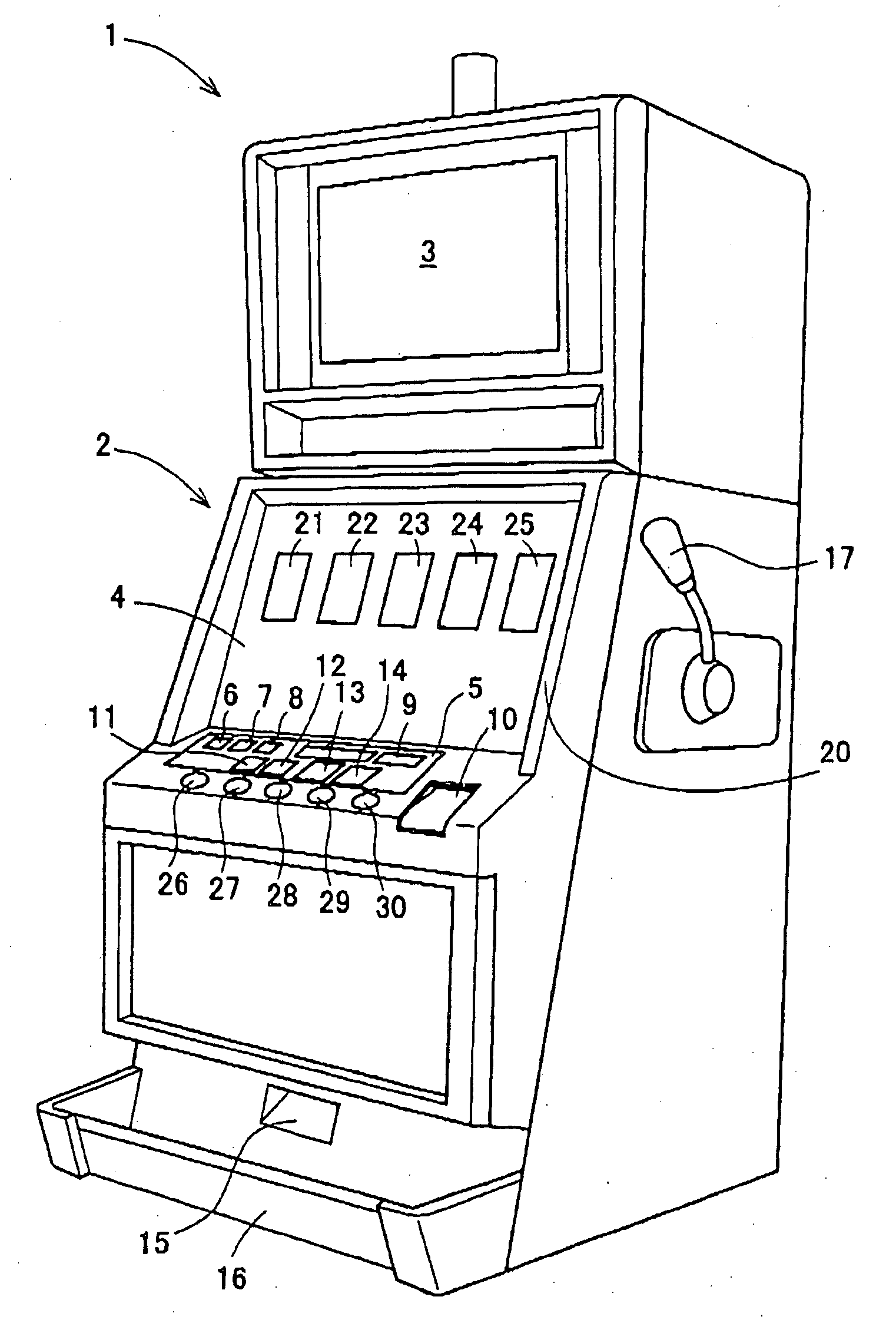
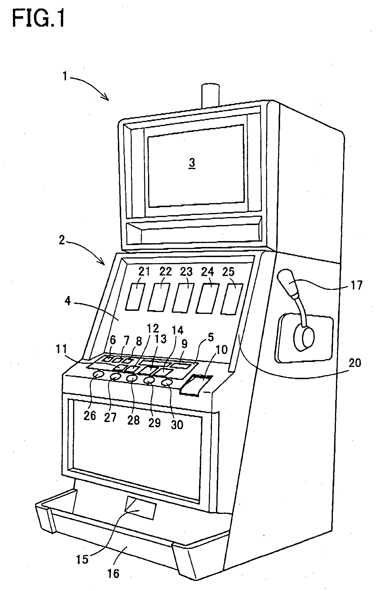
[0091] In the first embodiment, as for the free game mentioned hereinafter, the pay line L2 is determined to only the center line, and such pay line L2 is displayed on the lower liquid crystal display 4 when free game, in which at first each of the reels 220 is automatically rotated and continuously stopped based on press operation of the stop buttons 26 to 30, is conducted.

[0092] And the COLORLESS 7 symbol 193 can be colored in red color or blue color by the lower liquid crystal display 4, thereby there may be a case that the COLORLESS 7 symbol 193 is changed to the RED 7 symbol 191 or the BLUE 7 symbol 192.

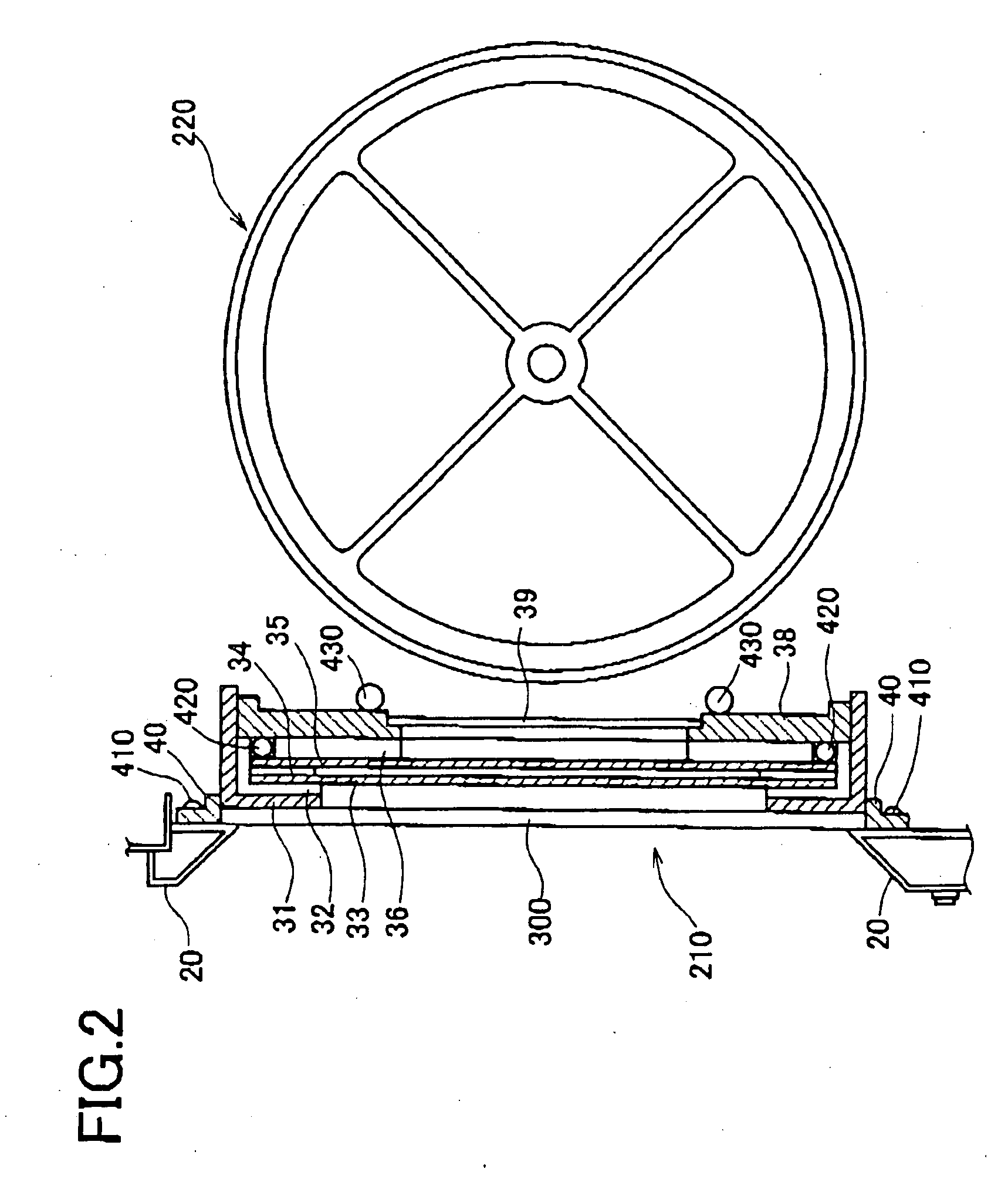
[0093] Next, construction of the lower liquid crystal display 4 will be described with reference to FIGS. 2 and 3A˜3I. In FIGS. 2 and 3A˜3I, the lower liquid crystal display 4 is constructed by arranging from the front side of the slot machine 1; the transparent touch panel 300, the reel glass base 31, the bezel metal frame 32, the transparent liquid crystal panel 33, the liqui...

second embodiment

[0171] Here, in the second embodiment, each of the stop buttons 26 to 30 has no relation with so-called “observation push” which is done for purpose to allow technical intervention by the player. And the switch signal output from each of the stop buttons 26 to 30 is used to the end only as the trigger when the symbols scrolled on the variable display portions 21 to 25 are stopped and displayed thereon. Therefore, the symbols on each of the variable display portions 21 to 25 are stopped and displayed thereon based on only the lottery result obtained in S2 of FIG. 21.

[0172] And in S48, coins corresponding to the payout which is set beforehand are paid out according to the symbol combination of the winning combination stopped and displayed over each of the variable display portions in S47. After process in S48 is done, the base game process is finished.

[0173] Next, the free game process done in S45 will be described with reference to FIG. 23. FIG. 23 shows a flowchart of the free game...


PUM


Abstract

It is disclosed the slot machine 1, in which when it is determined that the “colorless effect” process utilizing the colorless 7 symbol 193 is done (S33) and for example, the winning combination of the red 7-red 7-red 7 is won, two red 7 symbols are automatically stopped and displayed along the pay line, thereafter the colorless 7 symbol is stopped and displayed along the pay line (S37). Further, after 0.5 seconds are elapsed, red color is added to the colorless 7 symbol 193 by displaying red color in the area superimposing with the colorless 7 symbol 193, thereby the colorless 7 symbol 193 is displayed as the red 7 symbol (S38). And in the free game conducted continuous to the base game based on that the trigger thereof is realized, when the specific winning combination (red 7-red 7-TRIPLE or red 7-red 7-DOUBLE) is won, the red 7 symbols are stopped on the pay line on the left reel 220 and the center reel 220 and the first divisional symbol “LE”, which is obtained by dividing the word “TRIPLE” or DOUBLE” into two, is stopped, thereafter the symbols are scrolled on the variable display portion 24 corresponding to the right reel 220 and the other second divisional symbol “TRIP” or “DOUB”, which forms the word “TRIPLE” or “DOUBLE” in cooperation with the first divisional symbol “LE”, is stopped on the pay line.

Description

CROSS-REFERENCE TO THE RELATED APPLICATION(S) [0001] This application is based upon and claims a priority from the prior Japanese Patent Application Nos. 2003-199996 filed on Jul. 22, 2003, 2003-201071 filed on Jul. 24, 2003 and 2004-208363 filed on Jul. 15, 2004, the entire contents of which are incorporated herein by reference. This application is related to co-pending U.S. patent application entitled to “GAMING MACHINE WITH DISPLAY DEVICE FOR VARIABLY DISPLAYING SYMBOLS THEREON AND CAPABLE OF CHANGING NUMBER OR SHAPES OF SYMBOLS UNDER PREDETERMINED CONDITION”, which is based upon and claims a priority from the prior Japanese Patent Application Nos. 2003-199206 and 2003-199216 both of which were filed on Jul. 18, 2003 and the inventor of which is Motoaki TACHIKAWA BACKGROUND OF THE INVENTION [0002] 1. Field of the Invention [0003] The present invention relates to a gaming machine which gives predetermined benefit to a player when symbols on a plurality of variable display portions...

Claims


Application Information

Patent Timeline
IPC IPC(8): A63F5/04A63F9/24G07F17/32G07F17/34
CPCG07F17/3267G07F17/3211
Inventor TACHIKAWA, MOTOAKI
Owner UNIVERSAL ENTERTAINMENT CORP
Learn More