

Heat treatment apparatus and method
- Summary
- Abstract
- Description
- Claims
- Application Information
AI Technical Summary
Benefits of technology
Problems solved by technology
Method used
Image

Examples
first embodiment
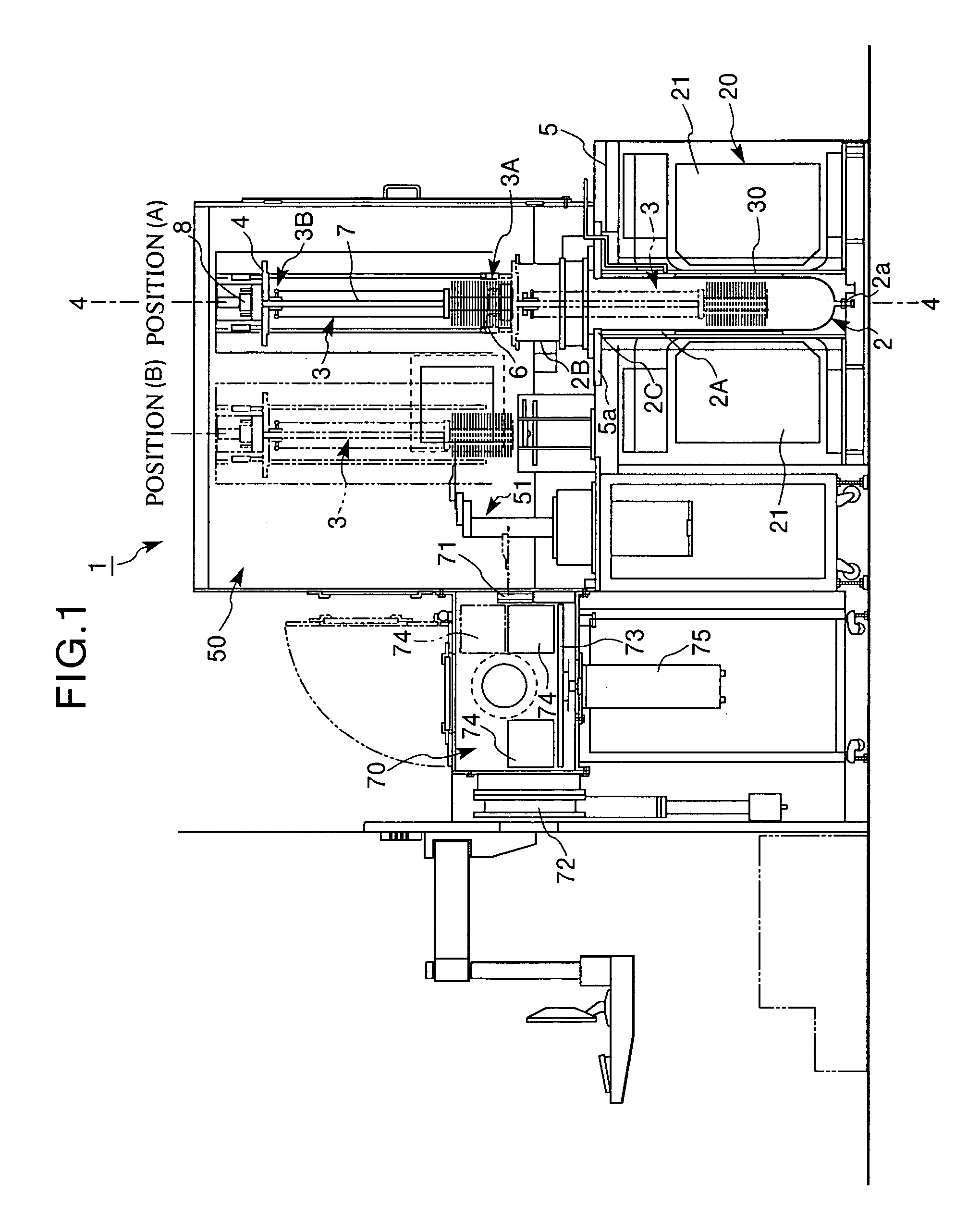
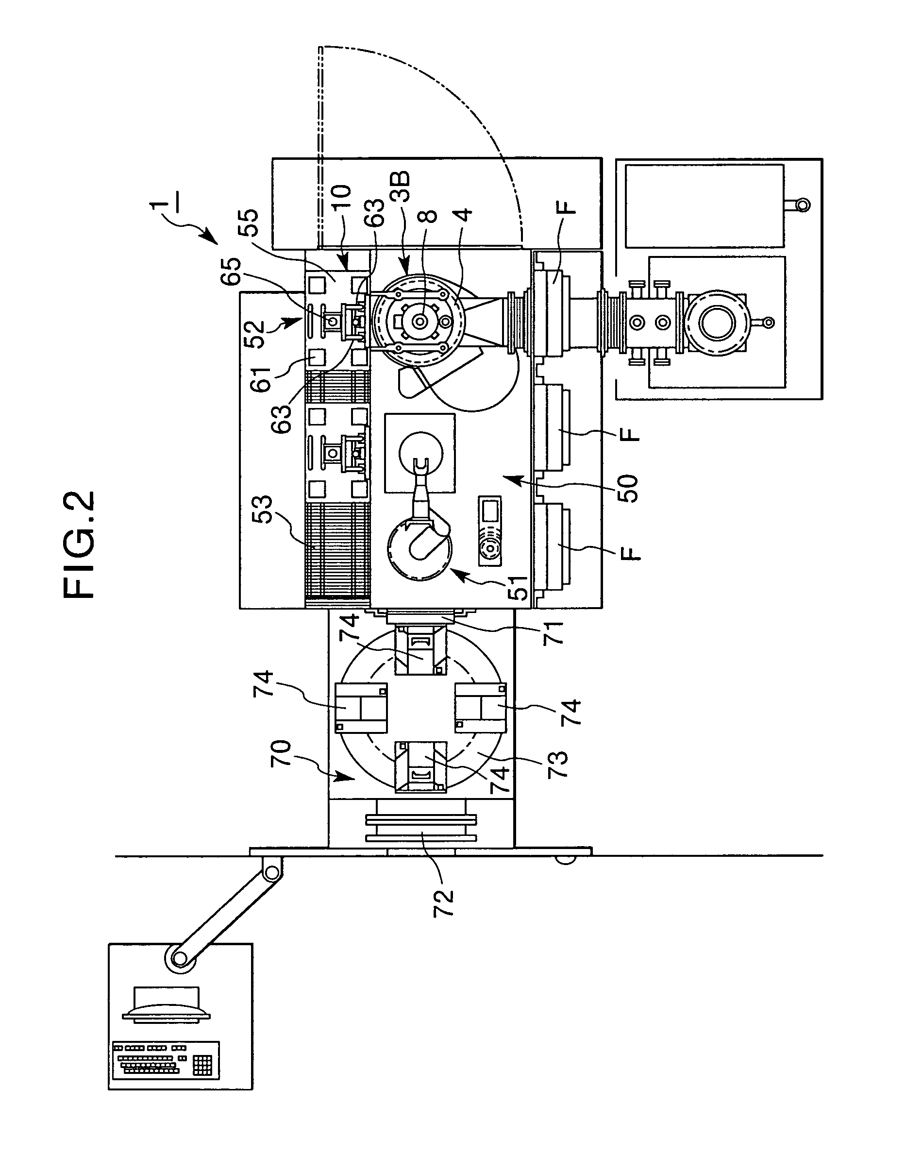
[0061] FIGS. 1 to 4 illustrate a schematic overall configuration of one embodiment of the heat treatment apparatus 1 of the invention.
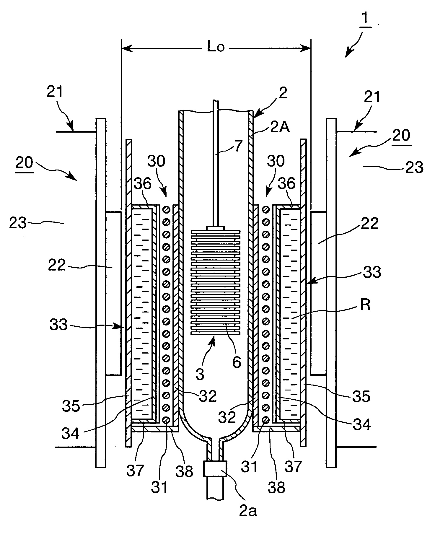
[0062] According to this embodiment, the heat treatment apparatus 1 has a vacuum vessel 2 serving as a heat treatment vessel, holding unit 3 which holds an object of treatment in the vacuum vessel 2, and magnetic field generator 20 arranged outside the vacuum vessel 2, as in the conventional heat treatment apparatus 1A. The holding unit 3 has a holder 3A which holds the object of treatment, and a holder supporting unit 3B which supports this holder 3A.
[0063] As is understood well by referring also to FIG. 5, in this embodiment, the vacuum vessel 2 is a stepped cylindrical container comprising a vessel main body 2A having a smaller diameter, and a vessel attachment section 2B having a larger diameter formed integrally with the upper portion of the vessel main body 2A. In this embodiment, the lower end of the vessel main body 2A is connected to a cond...
second embodiment
[0114] In the first embodiment, the description has been based on a configuration in which the treatment chamber 50 is located above the vacuum vessel 2, and the object of treatment travels between the heat treatment vessel 2 and the treatment chamber 50 by moving the same vertically via the holder supporting unit 3B and the holder 3A by the conveyor 10. In the second embodiment, in contrast, as shown in FIG. 10, the treatment chamber 50 is located below the vacuum vessel 2, and the object of treatment is movable between the heat treatment vessel 2 and the treatment chamber 50 by vertically moving the same via the holder supporting unit 3B and the holder 3A by the conveyor 10 as in the first embodiment.
[0115] Also in this embodiment, the same functional effects as in the first embodiment are available, and furthermore, in this embodiment, since the conveyor 10 and the like for moving the object of treatment are arranged below the vacuum vessel 2, there is available an advantage tha...
third embodiment
[0116] Unlike the first and the second embodiments, the third embodiment has a configuration in which, as shown in FIG. 11, the vacuum vessel 2 is horizontally arranged, and the treatment chamber 50 is positioned on a side of the vacuum vessel 2.
[0117] In this embodiment, the object of treatment travels between the heat treatment vessel 2 and the treatment chamber 50 through horizontal displacement via the holder supporting unit 3B and the holder 3A by the conveyor 10.
[0118] Also in this embodiment, there are available the same functional effects as in the first embodiment.
PUM
 Abstract
Description
Claims
Application Information