Humerus internal safe locking nail

a safe locking and humerus technology, applied in the field of nails, can solve the problems of not solving probable problems, increasing the risk of infection at the extra cut application, and often seeing arm fractures, so as to shorten the application and operation time, reduce the negative effects of existing structure, and improve the effect of safety

Active Publication Date: 2018-10-18
TST RAKOR & TIBBI ALETLER SANAYI & TICARET SIRKETI
View PDF9 Cites 0 Cited by
  • Summary
  • Abstract
  • Description
  • Claims
  • Application Information

AI Technical Summary

Benefits of technology

[0009]According to the way of the technique the aim of the invention is to develop a Humerus internal safe locking nail to eliminate the negativities of existing structure that brings faster and more effective solutions to the humerus fracture treatment.
[0010]Another object of the invention is to lock from inside out without having to cut the distal portion of the nail. In this way, all the problems are avoid that may arise in the distal portion.
[0011]Another object of the invention is the shortening of the application and operation time. In this way, an important contribution of the shortening of the treatment period is provided.

Problems solved by technology

Arm fractures are often seen in traffic accidents or falling on to the hands in an accident.
The risk of infection is increased at the extra cut applications.
But it does not solve the probable problems here, since it is necessary to make incision in order to achieve locking at the distal part.
There is an increasing risk of infection, probable injuries of radial nerve, median nerve and musculocutaneous nerve at the part of distal locking and this causes extended healing time.

Method used


Image

  • Humerus internal safe locking nail
  • Humerus internal safe locking nail

Examples


Embodiment Construction

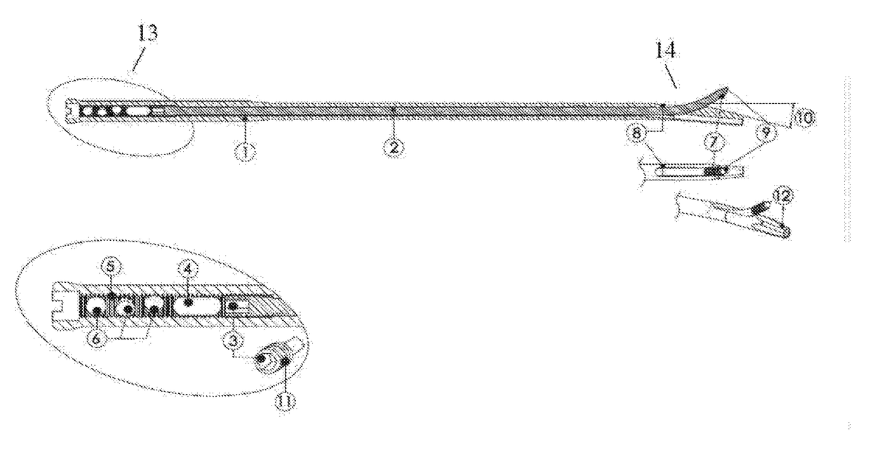
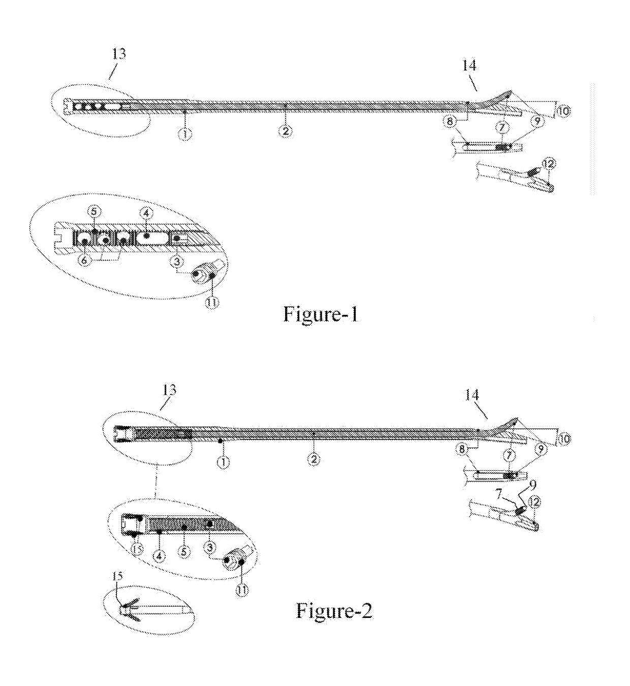
[0017]Invention, is about ulna internal safe locking nail (1), locking pin (2) is created that is mounted on the inside and allows locking at the distal portion. It has at the upper part (13) a compression hole of the nail (4), locking pin slot of the nail (5), angled screw holes on the proximal of the nail (6). It is locking at the distal of the humerus bone by screwing the bone entering tip of the locking pin (9) on the threaded end of the locking pin (7) which is coming out of the distal hole of the nail (8) at the lower part (14) moving with a screw driver from inside on the locking pin (2) over the locking pin sending slot (3). It has at the lower part (14) of the humerus internal safe locking nail (1) a rotation preventive end structure of the nail (12), distal hole of the nail (8). It has between the rotation preventive end structure of the nail (12) and the bone entering tip of the locking pin (9) on the humerus internal safe locking nail (1) the Anatomically angled tip on t...


PUM


Abstract

Invention is related to the nails used in the surgical treatment of humeral fractures. And it is characterized with, humerus internal safe locking nail (1) which is including; Locking pin (2) providing distal locking by outgoing from the distal hole of the nail (8) in pursuit of being screwed inside all along from the proximal of the humerus internal safe locking nail (1) At least one locking sending slot (3) on the locking pin (2) providing locking pin (2) to be sent to lock from the distal part At least one locking pin slot of the nail (5) on the proximal part of the humerus internal safe locking nail (1) providing locking pin (2) to proceed into humerus internal safe locking nail (1). At least one Threaded proximal part of the locking pin (11) on the locking pin (2) At least one threaded end of the locking pin (7) locking by outgoing from the distal hole of the nail on the locking pin (2) At least one Bone entering tip of the locking pin (9) providing locking by entering to the bone angularly on the threaded end of the locking pin (7) Anatomically angled tip on the distal part of the nail (10) in the form of curved and straight comprised on the distal part of the humerus internal safe locking nail (1). humerus internal safe locking nail (1) is characterized with humerus internal safe locking nail (1) including rotation preventive end structure of the nail (12) on the distal part.

Description

TECHNICAL SCOPE[0001]The current invention is about nails which are used in the surgical treatment of humerus fractures.[0002]The invention is especially related with the new humerus internal safe locking nails that eliminate the experienced problems in the treatment of humerus fractures.COMMON STATUS OF THE TECHNIQUE[0003]Humerus is located between scapula and olecranon and forms the bone structure of the arm region. Humerus fractures can be broken by direct impact and by axial loading from elbow direction. Humeral (arm) fractures are commonly seen. One of every 20 fractures is an arm (humeral) fracture. Children forearm fractures are more frequently seen then the arm fractures. Arm fractures are often seen in traffic accidents or falling on to the hands in an accident.[0004]Intramedullary nails can be used for the surgical treatment of humeral fractures.[0005]The patient is exposed to lots of radiation when a guide or fluoroscopy is need for the distal locking.[0006]In the present...

Claims


Application Information

Patent Timeline
Patent Type & Authority Applications(United States)
IPC IPC(8): A61B17/72
CPCA61B17/7266A61B17/725A61B2017/681A61B17/72A61B17/7233
Inventor AKPINAR, FUATPOLAT, AHMET FETHI
Owner TST RAKOR & TIBBI ALETLER SANAYI & TICARET SIRKETI
Why Eureka
Try Eureka