Passive gravity-compensating mechanisms

a gravity compensating mechanism and arm technology, applied in the direction of mechanical control devices, controlling members, building scaffolds, etc., can solve the problems of additional effort or energy, drooping arms, and at least double the space used, or at least add a mass

Inactive Publication Date: 2005-02-03
AGENCY FOR SCI TECH & RES
View PDF9 Cites 15 Cited by
  • Summary
  • Abstract
  • Description
  • Claims
  • Application Information

AI Technical Summary

Benefits of technology

Thus using the present invention, gravity compensation for a series of two linkage arms can be provided through a pair of non-circular gear profiles, with an end of each linkage arm connected to a separate gear set of two non-circular cam bodies, by way of separate cables. Springs in the gear sets provide tension in the cables. The tension in each cable varies according to the angle through which the cam bodies have turned as a result of the co-operating non-circular surfac...

Problems solved by technology

This tends to make the arm droop downwards and additional effort or energy is necessary to counteract or compensate for this.
The problem with this is that it either at least doubles t...

Method used


Image

  • Passive gravity-compensating mechanisms
  • Passive gravity-compensating mechanisms
  • Passive gravity-compensating mechanisms

Examples


first embodiment

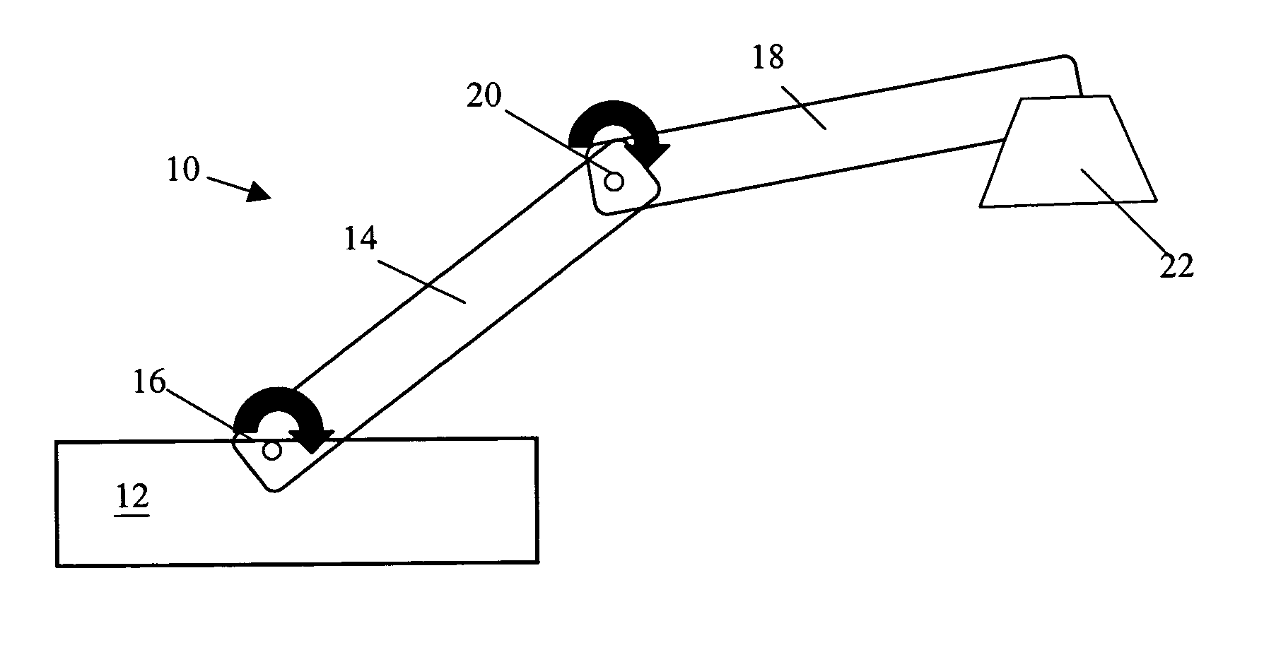
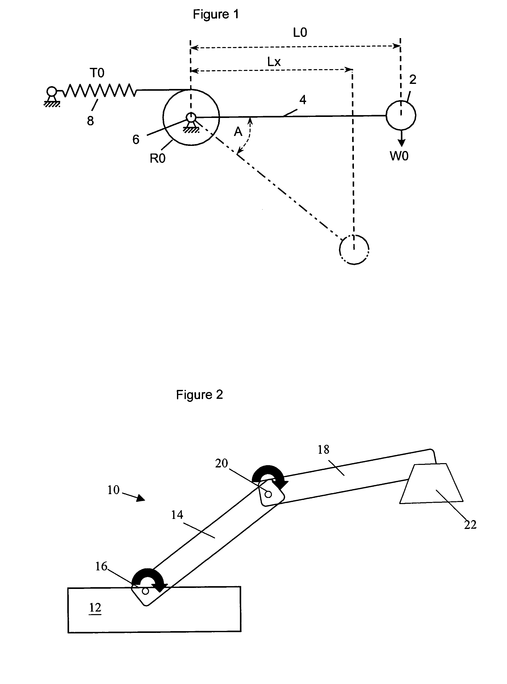
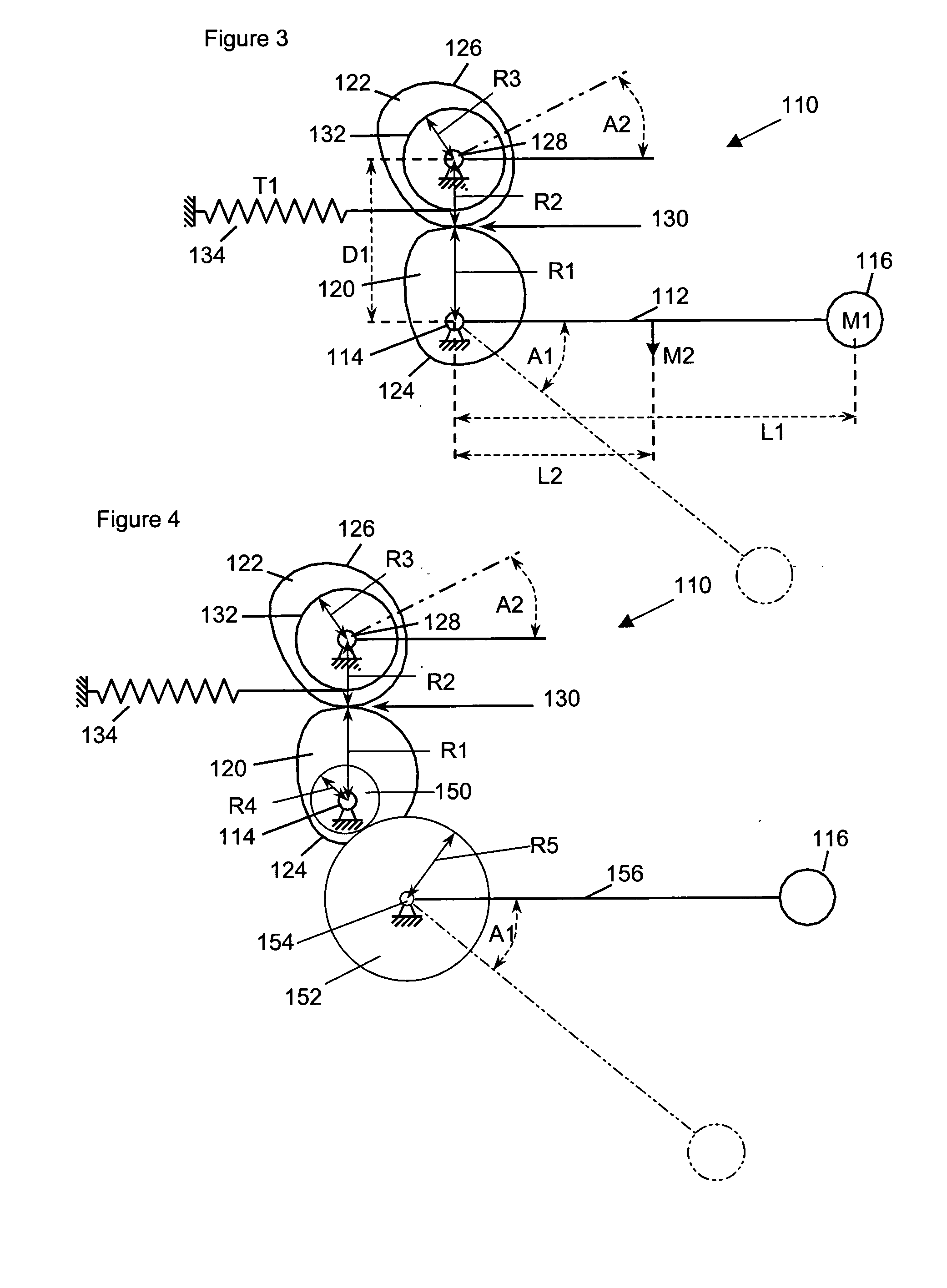
FIG. 3 shows a gravity compensated system 110 according to the invention.

A single arm 112 is mounted to rotate about a pivot point 114. The arm 112 has a length L1 with a mass M1 at its end 116. It also has its own mass M2, acting through its center of mass 118, at a distance L2 along the length of the arm 112. Assuming the arm is at an angle A1 to the horizontal, the moment about the pivot point 114, due to the arm 112 is:

([M1*L1]+[M2*L2])*g*Cos A1,

where “g” is the acceleration due to gravity.

The system 110 also includes two cam bodies 120, 122, with non-circular profiles in the form of non-circular outer surfaces 124, 126. A first cam body 120 rotates about the same pivot point 114 with the arm 112. The second cam body 122 rotates about a second pivot point 128. The non-circular outer surfaces 124, 126 remain in contact with each other, at a changing point of contact 130 (which always lies on a line directly between the first and second pivot points) and rotate with each oth...


PUM


Abstract

Mechanisms for passive gravity compensation for a system of linkage arms are provided. Gravity compensation is provided through a pair of non-circular gear profiles, with an end of each linkage arm connected to a separate gear set of two non-circular cam bodies, by way of separate cables. Springs in the gear sets provide tension in the cables. The tension in each cable varies according to the angle through which the cam bodies have turned as a result of the co-operating non-circular surfaces of the cam bodies. This, in turn is based on the amount the arms have turned and thereby allows the tension in the cables to compensate for the moments on the arms due to gravity, whatever angles they are at, independently of the angle of the other arm. To achieve this for the first arm of the linkage, the tension in the cable leading to the second arm of the linkage is also transmitted as a torque to the first arm through a pulley mounted on the rotation axis of the first arm.

Description

FIELD OF THE INVENTION This invention relates to passive gravity compensating mechanisms for arms, particularly in linkages, by using non-circular surface portions. The arms are supported at one end and are rotatable in the vertical plane with the other end not supported and not necessarily vertical. The invention is particularly useful for gravity compensating a system of multi-segment linkages, that is those having a number of arms. BACKGROUND TO THE INVENTION Arms which pivot in the vertical plane and are only supported in one place are well known and often used mechanisms. They can be just single arms lifting something at their distal ends or systems of multi-segment linkages, made up of several arms, each one pivotably linked but independently rotatable relative to the other in the vertical plane. In every case where the center of mass is not directly below (or above) the pivot point (and except where there is no force due to gravity) there is a moment about the pivot due to ...

Claims


Application Information

Patent Timeline
IPC IPC(8): E04G3/00
CPCY10T74/20F16F15/28
Inventor CHOW, SIEW LOONGSHI, CHENG FU
Owner AGENCY FOR SCI TECH & RES
Why Eureka
Try Eureka