

Tape winding method
a winding method and tape technology, applied in the direction of carrier storage means, record carrier guidance, thin material handling, etc., can solve the problem of difficult winding disturban
- Summary
- Abstract
- Description
- Claims
- Application Information
AI Technical Summary
Benefits of technology
Problems solved by technology
Method used
Image

Examples
first embodiment
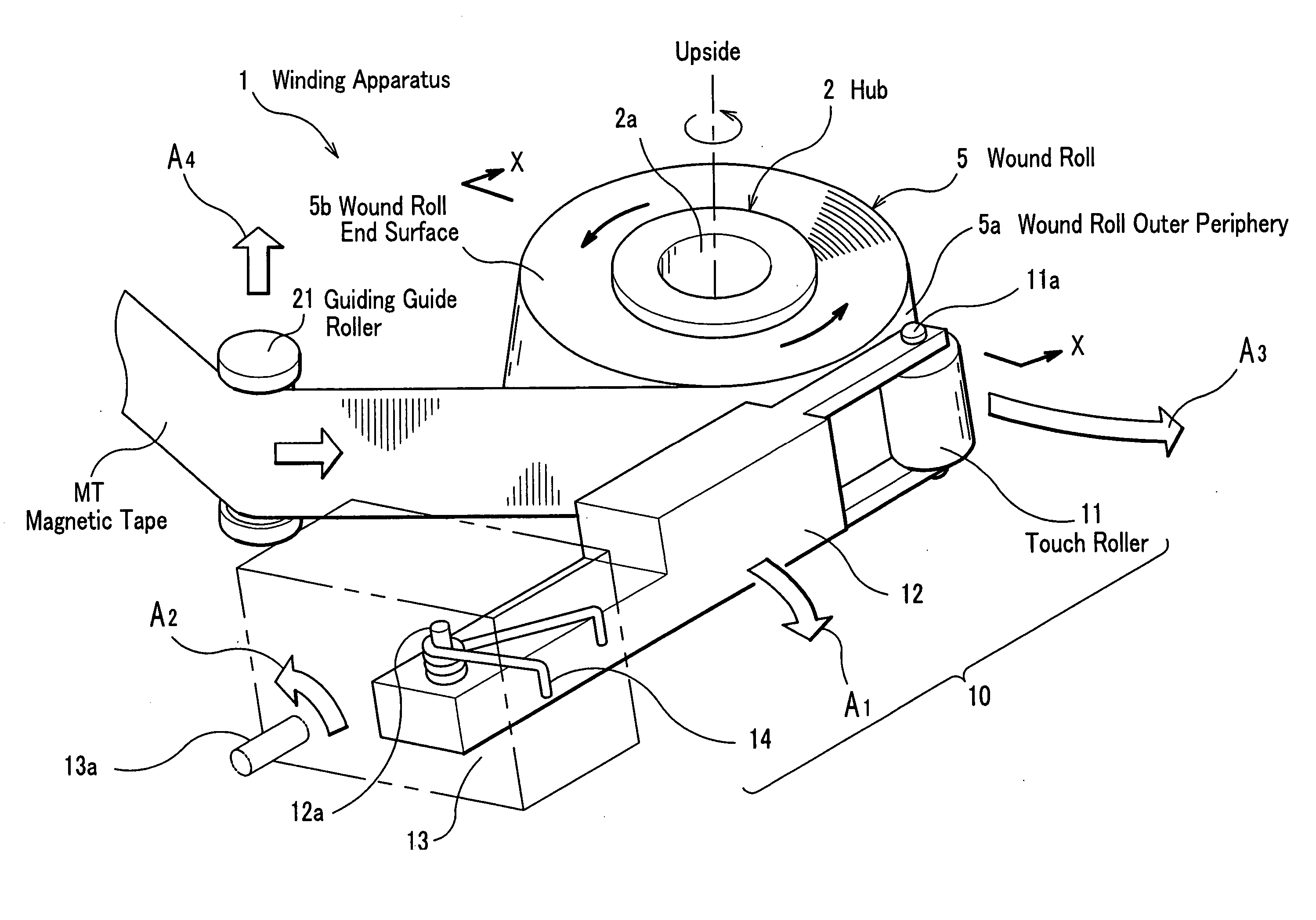
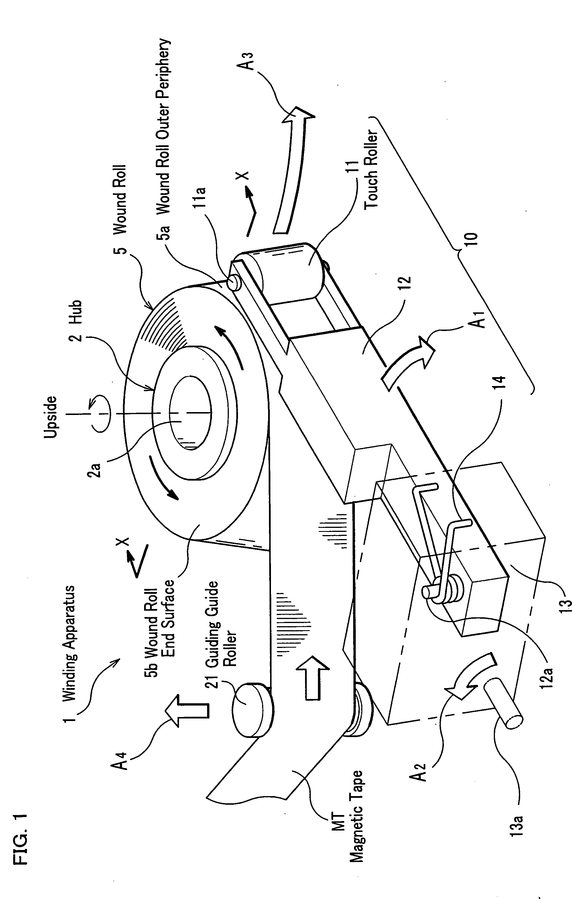
[0045] A tape winding method related to a first embodiment of the present invention will be described, referring to FIGS. 1 to 6.
[0046] Meanwhile, in the first embodiment, as shown in FIG. 1, an axial direction of a hub 2 is made an up / down direction, one end side thereof (upside shown inFIG. 1) is set the upside, the other end side (see FIGS. 3A, 3B, and the like) is set a downside, and magnetic tape MT is assumed to be wound on the hub 2 so that a wound roll end surface 5b at the upside of a wound roll 5 becomes concave. A touch roller 11 is also assumed to be same as above.
[0047] First, a configuration of a winding apparatus will be described, referring to FIG. 1.
[0048] As shown in FIG. 1, a winding apparatus 1 has the hub 2 for winding the magnetic tape MT and the touch roller 11, and is configured by comprising: a wound roll outer surface push means 10 for pushing a wound roll outer periphery 5a (tape surface of an outmost periphery), which is a periphery of the wound roll 5...
second embodiment
[0101] Subsequently, a tape winding method related to a second embodiment of the present invention will be described, referring to FIGS. 7, 8A, and 8B as needed.
[0102] The tape winding method related to the second embodiment is different in nothing but a winding process, compared to the tape winding method related to the first embodiment. In more detail, are different a configuration of a winding apparatus and a method for winding the magnetic tape MT on the hub 2. In the first embodiment the magnetic tape MT is wound and the touch roller 11 is moved like an arc; whereas, in the second embodiment the magnetic tape MT is wound while the hub 2 is moved like an arc for a touch roller 33 at a fixed position.
[0103] First, the configuration of the winding apparatus, which is used in the tape winding method related to the second embodiment, will be described, and then, the winding process by the winding apparatus will be described.
[0104] As shown in FIG. 7, a winding apparatus 30 relate...
third embodiment
[0113] Subsequently, a tape winding method related to a third embodiment of the present invention will be described, referring to FIGS. 9A and 9B.
[0114] The tape winding method related to the third embodiment is different in nothing but a winding process, compared to the tape winding method related to the first embodiment. In more detail, are different a configuration of a winding apparatus and a method for winding the magnetic tape MT on the hub 2. The third embodiment does not use the wound roll outer periphery push means 10 related to the first embodiment, attaches a winding guide 51 having a guide surface 51a to an upside end surface of the hub 2, and moves a guiding guide roller 23 to an upside as the magnetic tape MT is wound so that an upper edge of the magnetic tape MT is wound along the guide surface 51a (see an arrow mark A7 in FIG. 9A).
[0115] First, the configuration of the winding apparatus, which is used in the tape winding method related to the third embodiment, will...
PUM
| Property | Measurement | Unit |
|---|---|---|
| humidity | aaaaa | aaaaa |
| temperature | aaaaa | aaaaa |
| glass transition temperature | aaaaa | aaaaa |
Abstract
Description
Claims
Application Information