Pipe joint for refrigeration cycle

a technology for pipes and cycles, applied in the direction of hose connections, refrigeration components, light and heating equipment, etc., can solve the problem that/sub>refrigerant cannot be sufficiently used, and achieve the effect of excellent sealing properties

Inactive Publication Date: 2005-02-03
DENSO CORP
View PDF6 Cites 36 Cited by
  • Summary
  • Abstract
  • Description
  • Claims
  • Application Information

AI Technical Summary

Benefits of technology

[0010] In view of the above conventional problem, the object of the present invention ...

Problems solved by technology

However, when the above-described structure of the pipe joint is used in the CO2 refrigerant system, the CO2 refrigerant cannot be sufficiently prevented from leakin...

Method used


Image

  • Pipe joint for refrigeration cycle
  • Pipe joint for refrigeration cycle
  • Pipe joint for refrigeration cycle

Examples


Embodiment Construction

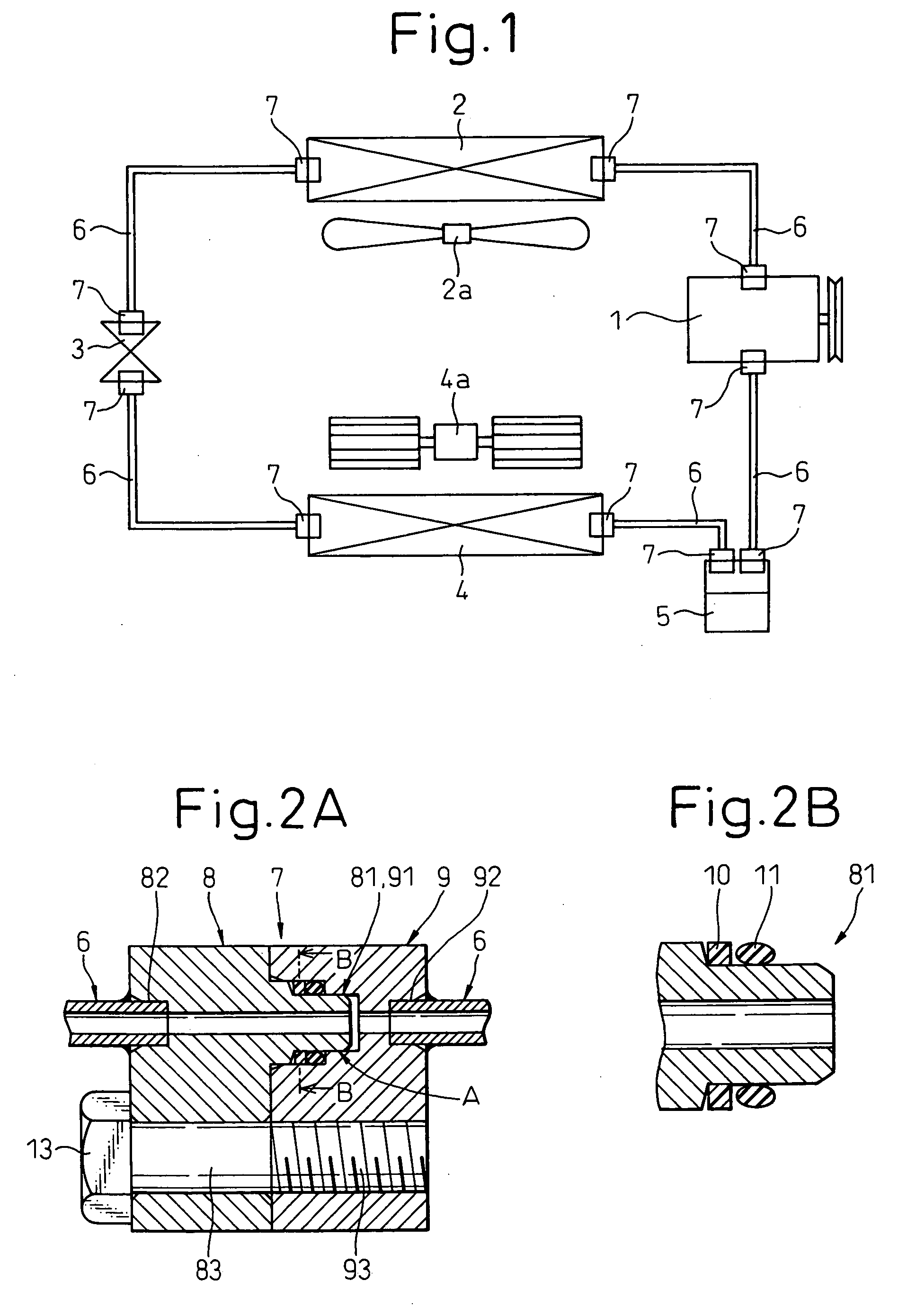
[0040] Embodiments of the present invention will be described below with reference to the drawings. First, a first embodiment will be described. FIG. 1 is a schematic view of an embodiment of a refrigeration cycle R according to the present invention. The refrigeration cycle R, in which refrigerator devices including a refrigerant compressor 1, a refrigerant condenser 2, an expansion valve 3, a refrigerant evaporator 4, an accumulator 5, etc. are connected in a loop, is well known. Specifically, these devices are connected by refrigerant pipes 6 having pipe joints 7. In FIG. 1, numeral 2a designates an air blower which supplies air for a heat exchange, to the refrigerant condenser 2; and 4a designates an air blower which supplies air for a heat exchange, to the refrigerant evaporator 4.

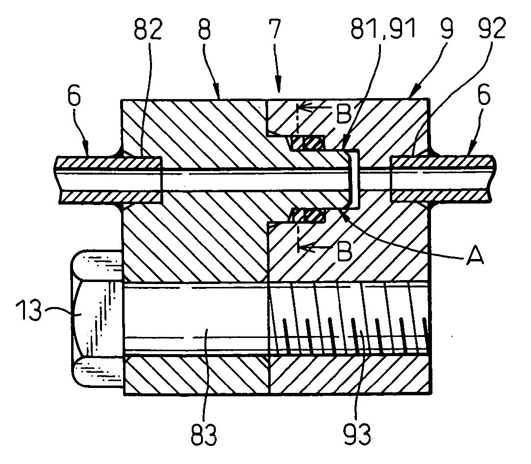
[0041]FIG. 2A is a sectional view of a first embodiment of a refrigeration cycle pipe joint 7 (hereinafter referred to as “pipe joint 7”) in a joined state, according to the present invention. FIG. 2...


PUM


Abstract

The front end portion of a fitting projection from the portion on which a backup ring is mounted to the front end, has a diameter smaller than the inner diameter of the backup ring. The backup ring is endless in the circumferential direction thereof. A bias cut of the backup ring is not required when the backup ring is fitted on the fitting projection and, accordingly, the endless backup ring which continuously extends in a circumferential direction can be used. Therefore, the backup ring can also function as a sealing member and, thus, the refrigeration cycle pipe joint having the excellent refrigerant sealing property can be obtained. Consequently, a necessary amount of a refrigerant can be reduced because the amount of a refrigerant which permeates to the atmosphere is reduced, and the size of a receiver or an accumulator, having a refrigerant storing function, can be reduced.

Description

BACKGROUND OF THE INVENTION [0001] 1. Field of the Invention [0002] The present invention relates to a pipe joint for a refrigeration cycle, used for joining refrigerant passages of a refrigeration cycle. [0003] 2. Description of the Related Art [0004] Recently, a refrigeration cycle using carbon dioxide (CO2), as a refrigerant, has been developed instead of using chlorofluorocarbons. In the system using the CO2 refrigerant, pipes are used for joining refrigerator devices, and pipe joints are used for joining pipes and refrigerator devices or joining pipes, in a manner similar to a conventional system. The applicant has filed a pipe joint used in a conventional refrigeration cycle apparatus previously. [0005]FIG. 11 is a sectional view of a conventional refrigeration cycle pipe joint 7. As shown in the drawing, the pipe joint 7 is composed of a male joint portion 8 and a female joint portion 9, and has a cylindrical sealing structure in which an O-ring 11 is basically used. A cylind...

Claims


Application Information

Patent Timeline
IPC IPC(8): F16L19/03F16L13/08F16L23/024F16L23/032F16L23/16F25B9/00F25B41/00F28F9/04F28F9/26
CPCF16L13/08F16L23/024F16L23/032F25B9/008F25B41/003F28F9/26F25B2500/221F28F9/0246F28F9/0251F28F9/0256F25B2309/061F25B41/40Y10S285/918
Inventor TAKEUCHI, MASAYUKITOMATSU, YOSHITAKA
Owner DENSO CORP
Why Eureka
Try Eureka