Offset connector with compressible conductor

Inactive Publication Date: 2005-02-03
OL SECURITY LIABILITY CO
View PDF9 Cites 1 Cited by
  • Summary
  • Abstract
  • Description
  • Claims
  • Application Information

AI Technical Summary

Problems solved by technology

Bent pins, by themselves, do not provide the z-axis float needed to accommodate tolerance build up.
Using a socket can require pins on the mating component, which could create yield problems due, at least in part, to pin misalignment and irregularities.

Method used


Image

  • Offset connector with compressible conductor
  • Offset connector with compressible conductor
  • Offset connector with compressible conductor

Examples


Embodiment Construction

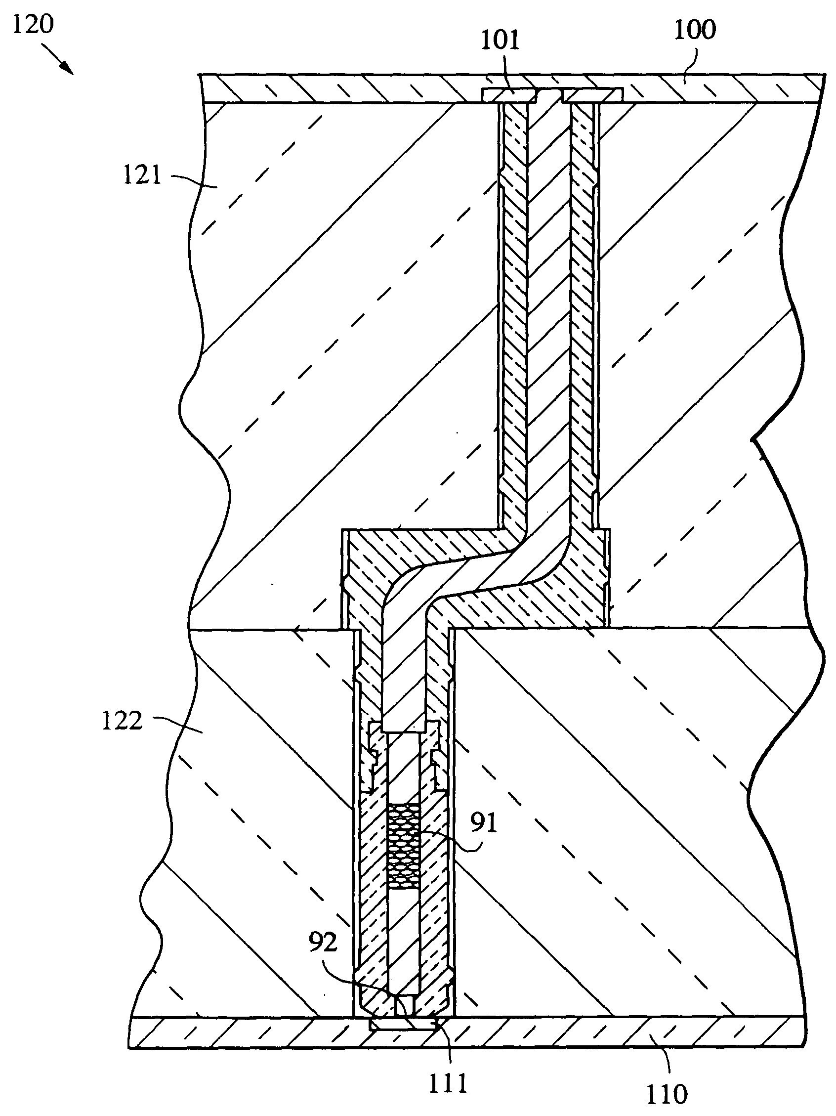
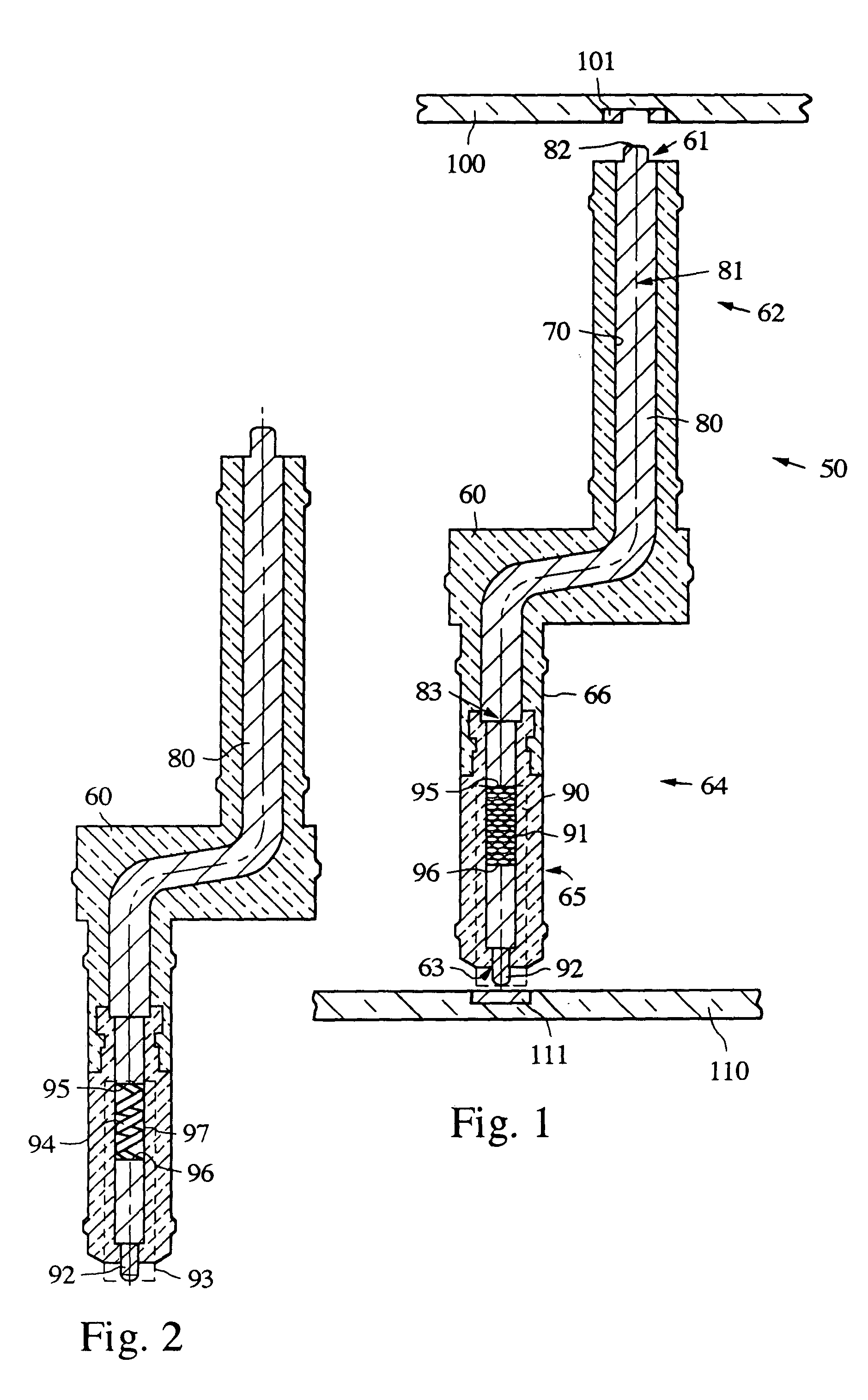
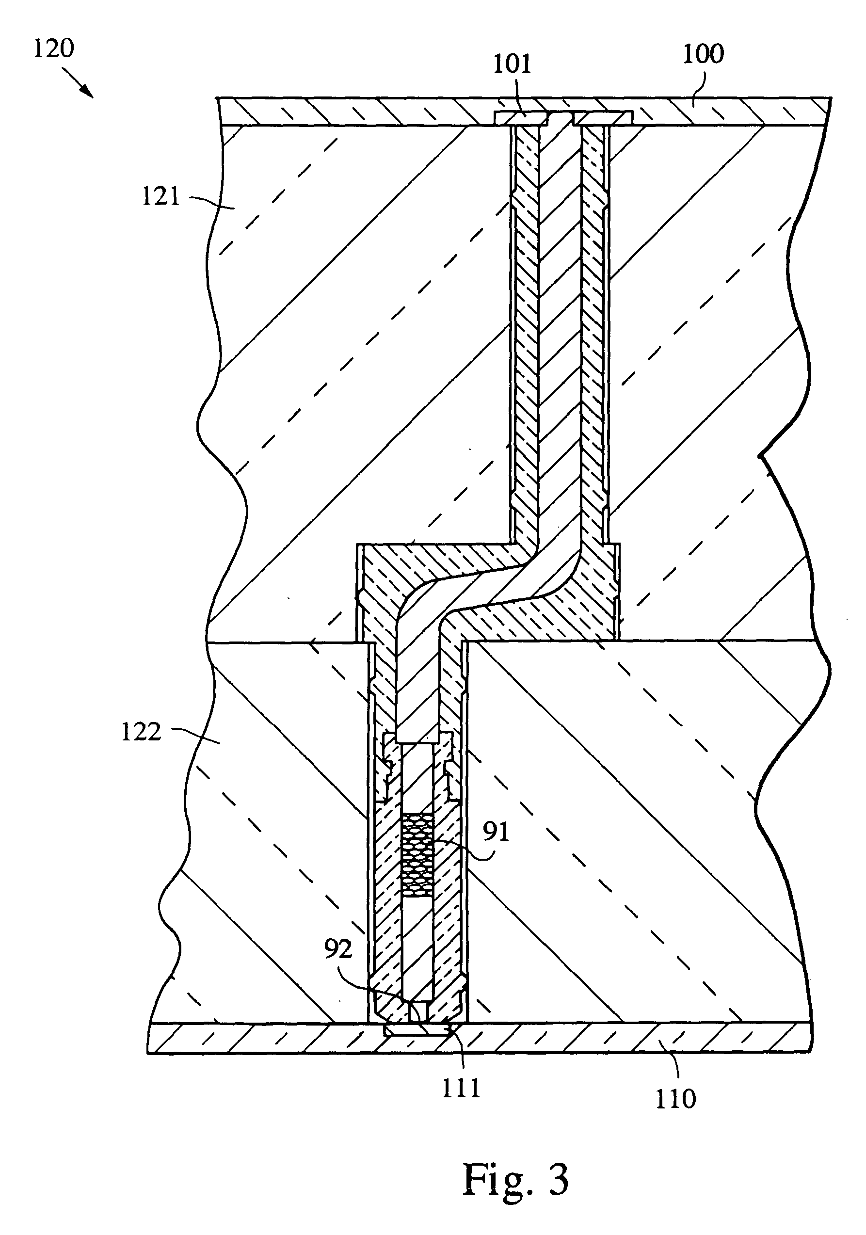
[0012] The connector of the disclosure may be used to connect a first mating portion of a first component with a second mating portion of a second component. The first mating portion and the second mating portion may be offset or off-grid from one another.

[0013] The connector provides a robust and simple electrical connection which may also be impedance controlled and could be used wherever RF or digital interconnects are used. The desired characteristic impedance of the entire electrical path in a particular application may be chosen by appropriate selection of factors which may include the diameters of the compressible conductor, the electrical conductive path, the outside diameter of the dielectric body and the diameter of the internal cavity within the dielectric body and the dielectric constant of the dielectric. For example, an exemplary characteristic impedance could be 50 ohms. In an exemplary embodiment, the connectors are suitable for use in RF connections with frequencie...


PUM


Abstract

A connector providing an offset interconnect has a dielectric body with first and second longitudinally opposed and laterally offset portions and an internal cavity. An offset electrically conductive path is disposed within the internal cavity. The offset electrically conductive path extends from the first portion of the dielectric body to the second portion of the dielectric body. A compressible conductor is disposed within the internal cavity in the second portion of the dielectric body.

Description

BACKGROUND OF THE DISCLOSURE [0001] The continued reduction in size of RF and other electrical components creates a need for compact RF connections that meet both electrical and mechanical requirements. Some microwave applications require an RF interconnection between adjacent components. The adjacent components may be substrates or circuit boards comprising layers in a stacked assembly. Connectors suitable for RF connections may also be suitable for digital (DC) signals. [0002] RF interconnects may be used to connect a mating portion of one component to a corresponding mating portion of another component. The corresponding mating portions may comprise elements of a grid pattern on one or both components. If the mating portions of the two components are on-grid with one another when in the assembled condition, the mating portions can be connected by a straight connector. [0003] RF interconnects used to provide straight connections between layers in a stacked assembly include various...

Claims


Application Information

Patent Timeline
IPC IPC(8): H01R12/71H01R13/24
CPCH01R13/2421H01R12/714H01R13/2471H01R12/73H01R13/24
Inventor WINSLOW, DAVID T.TALLMAN, COLLEENKEESEY, TIMOTHYTREINEN, JAMES P.CROCKETT, JOHN A.
Owner OL SECURITY LIABILITY CO
Why Eureka
Try Eureka