E-field monitor for broadband pulsed

a technology of e-field monitor and broadband pulse, which is applied in the direction of frequency analysis, instruments, measurement devices, etc., can solve the problems of increasing the potential to cause interference and/or corruption of exposed electronic equipment, the inability to continuously capture and measure all narrow pulsed radar emissions, and the complexity and expense of known systems

Inactive Publication Date: 2005-02-03
THE BOEING CO
View PDF9 Cites 7 Cited by
  • Summary
  • Abstract
  • Description
  • Claims
  • Application Information

AI Technical Summary

Benefits of technology

[0005] In one preferred embodiment of the present invention a system is provided for substantially continuously monitoring the electromagnetic intensity of short bursts of electromagnetic waves (E-waves) having frequencies within a very broad frequency range. The system includes at least one antenna capable of detecting one or more bursts of E-waves and converting the bursts into radio frequency (RF) signals having an energy level correlated to the intensities of the E-waves. The system additionally includes at least one broadband equalizer that normalizes the energy levels of RF signals across the broad range of frequencies. The system further includes at least one amplifier that amplifies the energy levels of the RF signals output by the broadband equalizer. Further yet, the system includes at least one RF peak power sensor for measuring the energy levels of the RF signals output from the amplifier and determining the peak power level of at least one peak RF signal that has the highest energy level. Still further, the system includes at least one power meter that converts the output of peak power sensor into power units. The power meter communicates the power measurements to a computer based device that converts the power measurements to E-wave energy units that indicate the strength of the E-wave correlated with the peak RF signal. If the strength of the E-wave exceeds a predetermined limit, the time and strength of the E-wave is recorded by the computer based device.

Problems solved by technology

These E-fields can potentially cause electronic interference with and / or corruption of electronic equipment exposed to the E-fields.
More specifically, the greater the intensity of the E-fields, the greater the potential to cause interference and / or corruption of exposed electronic equipment.
Known systems, of moderate complexity and expense, for detecting E-fields generally can not continuously capture and measure all narrow pulsed radar emissions, e.g. pulses having a duration of equal to or greater than 300 nsec, over a broad frequency range, e.g. 1 to 10 GHz.
For example, some known systems can only sample the E-field environment and consequently miss many radar pulses and / or they are unable to adequately detect narrow radar pulses over a broad frequency range.

Method used


Image

  • E-field monitor for broadband pulsed
  • E-field monitor for broadband pulsed
  • E-field monitor for broadband pulsed

Examples


Embodiment Construction

[0013] The description of the invention below is merely exemplary in nature and, thus, variations that do not depart from the gist of the invention are intended to be within the scope of the invention. Such variations are not to be regarded as a departure from the spirit and scope of the invention.

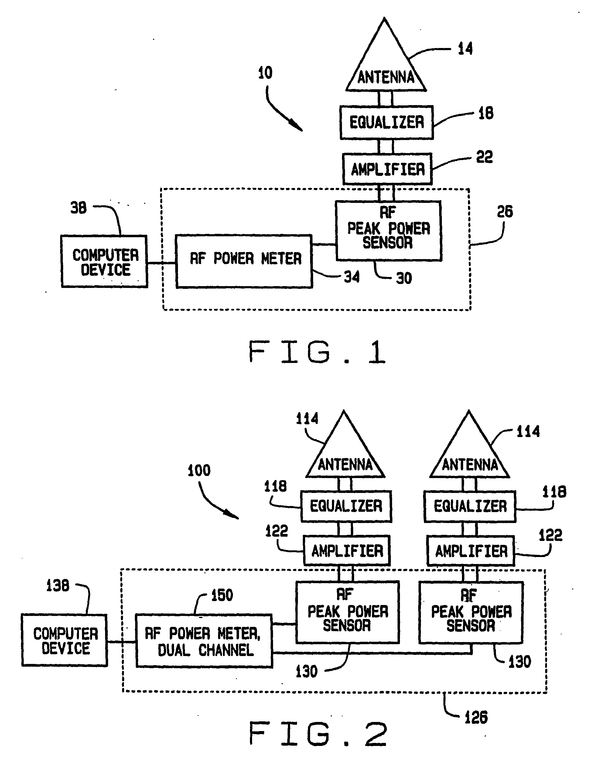
[0014]FIG. 1 is a block diagram of an E-field monitoring system 10, in accordance with a preferred embodiment of the present invention. The system 10 includes an antenna 14 that detects one or more E-fields and converts the E-fields into radio frequency (RF) signals. The antenna 14 is capable of sensing E-fields having frequencies within a very broad frequency range, for example 1 to 10 GHz. Preferably, the antenna 14 is an omni-directional antenna, however, antenna 14 can be any antenna suitable for receiving narrow pulsed E-fields with a broad frequency range. For example, antenna 14 can be a uni-directional antenna if it is desirable to sense E-fields from only one direction. Additiona...


PUM


Abstract

A system is provided for substantially continuously monitoring an electromagnetic intensity of short bursts of electromagnetic waves (E-waves) having frequencies within a broad frequency range. The system includes at least one antenna capable of detecting one or more bursts of E-waves and converting the bursts into radio frequency (RF) signals having an energy level correlated to the intensities of the E-waves. The system additionally includes at least one broadband equalizer that normalizes the energy levels of RF signals across the broad range of frequencies and at least one amplifier that amplifies the energy levels of the RF signals output by the broadband equalizer. The system further includes at least one RF peak power sensor for measuring the energy levels of the RF signals output from the amplifier and determining the peak power level of at least one peak RF signal that has the highest energy level. Further yet, the system includes at least one power meter that converts the peak power level of the peak RF signal to power units and a computer based device that utilizes the power units output by the peak power measurement subsystem to determine the strength of the E-wave correlated with the peak RF signal.

Description

STATEMENT OF GOVERNMENT RIGHTS [0001] This invention was developed at least in part pursuant to Contract No. F04701-97-C-0004, with the U.S Air Force. The U.S. Government has certain rights in this invention.FIELD OF THE INVENTION [0002] The present invention relates to narrow pulsed electromagnetic fields, or waves, generated by high power radio frequency (RF) emitters, such as radars. More specifically, the invention relates to a system for detecting the presence of such electromagnetic fields near electronic equipment that is vulnerable to anomalies causes by the electromagnetic fields. BACKGROUND OF THE INVENTION [0003] High power emitters, such as radars, emit narrow pulsed electromagnetic fields (E-fields), also referred to in the art as electromagnetic waves (E-waves), over a very broad frequency range. These E-fields can potentially cause electronic interference with and / or corruption of electronic equipment exposed to the E-fields. More specifically, the greater the intensi...

Claims


Application Information

Patent Timeline
Patent Type & Authority Applications(United States)
IPC IPC(8): G01R29/08G01S7/02
CPCG01S7/021G01R29/0814
Inventor JOHNSTON, GARY P.
Owner THE BOEING CO
Why Eureka
Try Eureka