Photoprinter control of peripheral devices

a technology of peripheral devices and photoprinters, applied in the field of photoprinter equipment, can solve the problems of image capture, non-portable, expensive, complicated,

a technology of peripheral devices and photoprinters, applied in the field of photoprinter equipment, can solve the problems of image capture, non-portable, expensive, complicated,

US20050024499A1Active Publication Date: 2005-02-03LEXMARK INT INC

Image

  • Photoprinter control of peripheral devices
  • Photoprinter control of peripheral devices
  • Photoprinter control of peripheral devices

Examples


Embodiment Construction

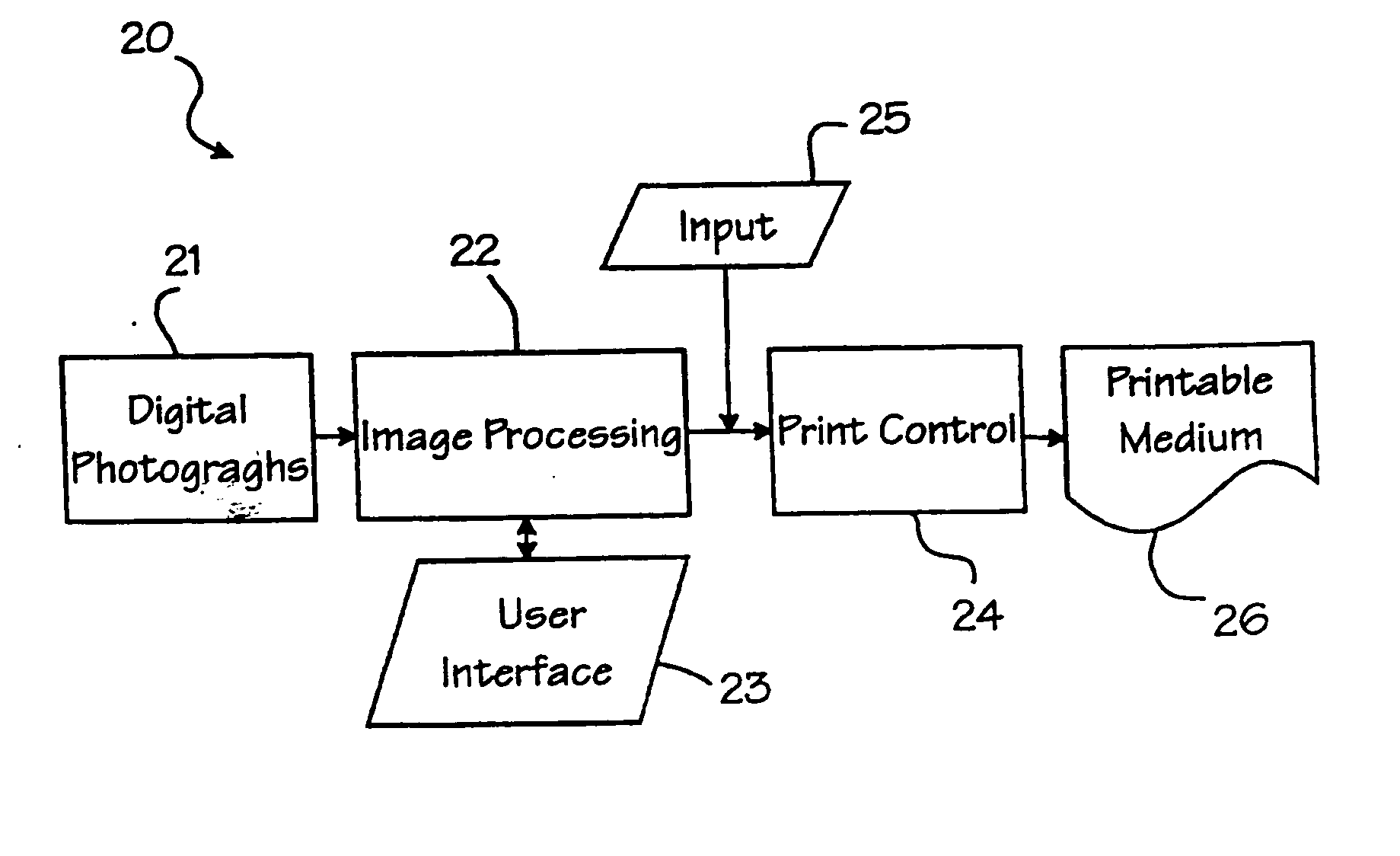
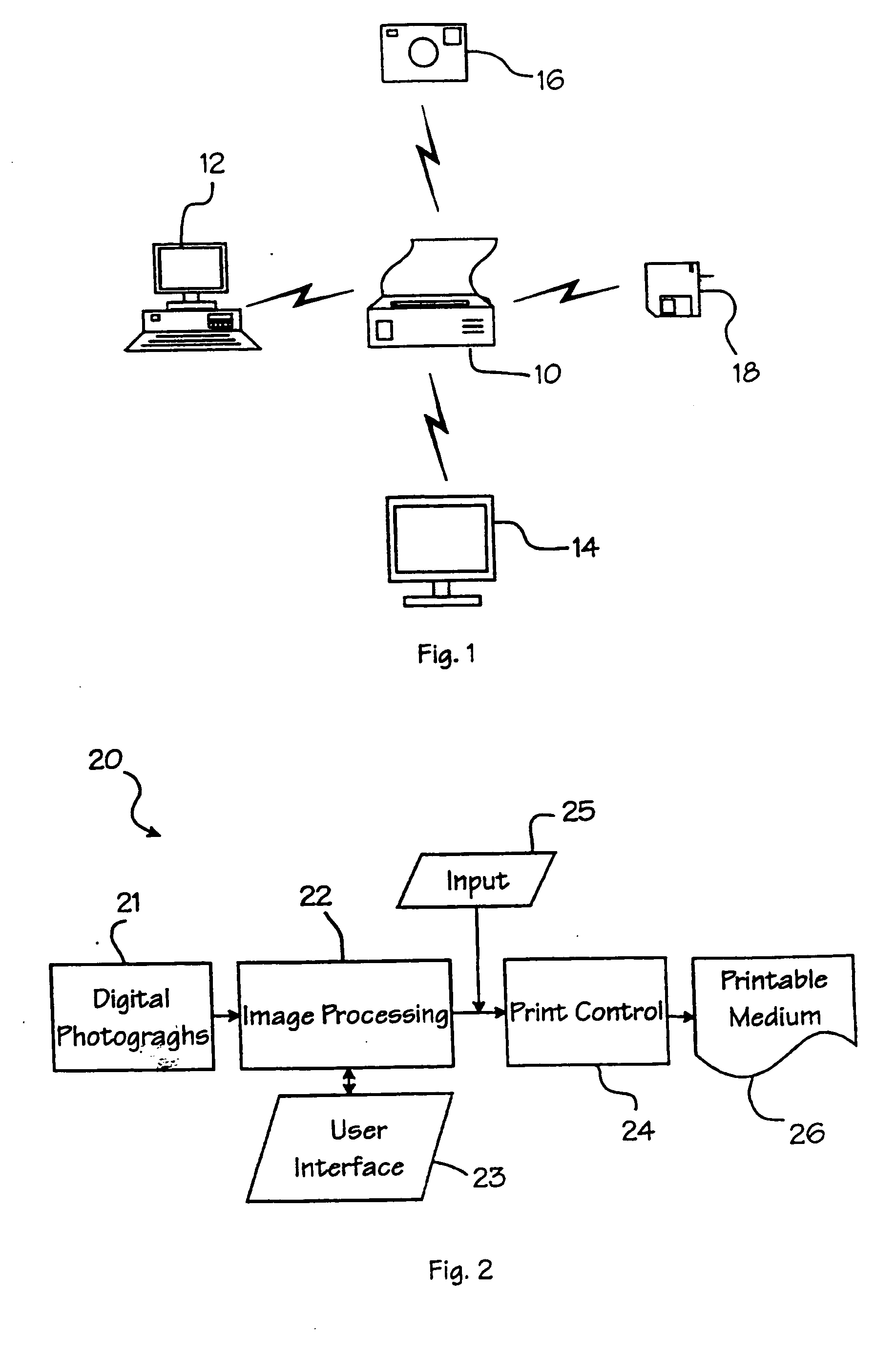
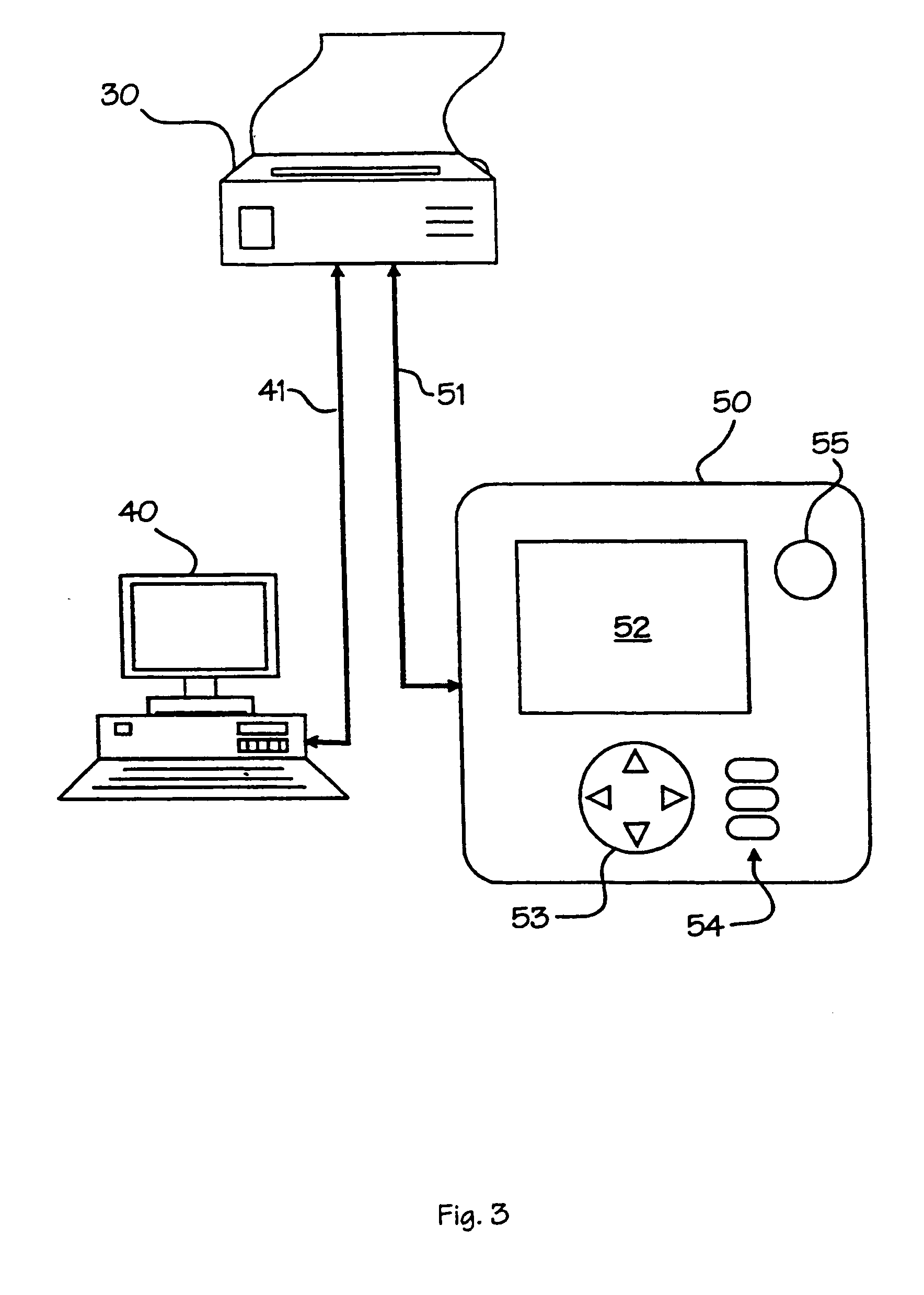
[0015] Reference will now be made to the present preferred embodiment of the invention, an example of which is illustrated in the accompanying drawings, wherein like numerals indicate the same element throughout the views. FIG. 1 illustrates one embodiment of a photoprinter 10. As used herein, a “photoprinter” refers to a stand-alone appliance for printing digital photographs onto a printable medium. A “digital photograph” is a photographic image captured by a light sensing electronic device (e.g., CCD, CMOS, CID, or the like) and converted into a digital file capable of being stored on a computer readable media. The term “stand-alone” means that the printer is capable of processing and printing digital files independent of external host device, such as a computer, wherein “processing” means calculating a pixel pattern to be printed on the printable medium that represents the corresponding digital file (sometimes referred to as “ripping” or generating printing code). For instance, a...


PUM


Abstract

A photoprinter configuration comprising a digital camera having a viewable display and one or more selection mechanisms. A photoprinter is connected to the digital camera via a communication link, wherein the photoprinter is operative to control the viewable display of the digital camera. Preferably, the photoprinter is further operative to direct the results from a user's inputs to the selection mechanisms of the digital camera. The photoprinter is operable as a client to a host computer, as a host for the digital camera, and a passthrough device such that the host computer may initiate requests to the digital camera.

Description

TECHNICAL FIELD [0001] This invention relates to the field of printer apparatuses and methods for using the same, and will be specifically disclosed in the context of stand-alone printers adapted to print digital photographs. BACKGROUND OF THE INVENTION [0002] The advent of computers have fundamentally changed the way images can be stored, manipulated, and printed. Images can now be captured by digital devices, such as digital cameras and scanners, and stored digitally. A digitally stored image can then be transmitted, enhanced, and manipulated through computer programs. Moreover, as digital technology has improved and associated costs fallen, the resolution of the images captured by these devices continues to improve, and in many cases approaches or exceeds the quality of traditional film photography. [0003] Traditionally, to use a digital image one needed a computer. The computer would be loaded with a variety of different programs to transit, enhance and manipulate the digital im...

Claims


Application Information

Patent Timeline
03 Feb 2005
Publication
US20050024499A1
IPC
B41J29/38; B41J29/00; H04N1/00; H04N5/225; H04N5/232; H04N101/00
CPC
H04N1/00204; H04N1/00347; H04N1/00408; H04N2101/00; H04N2201/0084; H04N2201/0055; H04N2201/0074; H04N2201/0082
Inventors
LUCIANO, JOSEPH W.; RADEMACHER, TIMOTHY J.