
Housing assembly for stacking multiple computer modules

a computer module and assembly technology, applied in the direction of furniture parts, electrical apparatus casings/cabinets/drawers, instruments, etc., can solve the problems of large space occupation, difficult service and upgrade, and stacking whole computer modules in a vertical position

Inactive Publication Date: 2005-02-03
ARIPPOL DERICK
View PDF6 Cites 12 Cited by
  • Summary
  • Abstract
  • Description
  • Claims
  • Application Information

AI Technical Summary

Benefits of technology

[0019] Typically, the railings of the assembly include more than one layer. In certain cases, the railings include a first layer, a second layer, a third layer and a fourth layer. In such cases, the first layer is typically a conducting material; the second layer is typically a non-conducting material that overlays the first layer and that includes a first side and a second side; the third layer is typically a conducting material placed on the first side of the second layer; and, the fourth layer is typically a non-conducting material. The first side of the second layer is usually opposite to the second side of the second layer. The s

Problems solved by technology

One problem with this method is that it stacks whole computer modules in a vertical position.
This type of stacking consumes large amounts of space and is very costly.
It is expensive, it requires a compact Motherboard-CPU configuration (height cannot exceed 4.3 cm which is the generic height for the Rack-Mount), it is heavy (enclosed onto a metal box with its own CPU-cooling system, memory and Power-Supply), and it is difficult to service and upgrade since the internal parts of each computer module are enclosed into their own box and not easily accessible.
This system still presents many downsides.
The system is still expensive due to the partial metal wrapping and type of housing used and each module requires its own power supply.
The computer modules are still heavy due to the weight of the partial metal wrapping and still consume a large space for storage.
The cooling system only works if all the computer modules are inserted in place, if one of the computer modules is pulled out, the air-flow is interrupted and some of the computer modules over-heat.

Method used


Image

  • Housing assembly for stacking multiple computer modules
  • Housing assembly for stacking multiple computer modules
  • Housing assembly for stacking multiple computer modules

Examples


Embodiment Construction

[0040] The invention is directed towards assemblies of electrical or electronic circuit boards. More specifically, the present invention relates to modular assemblies for housing multiple computer circuit boards. The assembly includes a housing that has several railing coupled to the housing. A connector is structurally and electrically coupled to the railings for hanging the computer circuit boards. Structural coupling between the connector and the railing is accomplished by placing the connector in contact with the railing in a file hanging method. This contact also creates an electrical coupling and establishes an electrical connection between the connector and the railing.

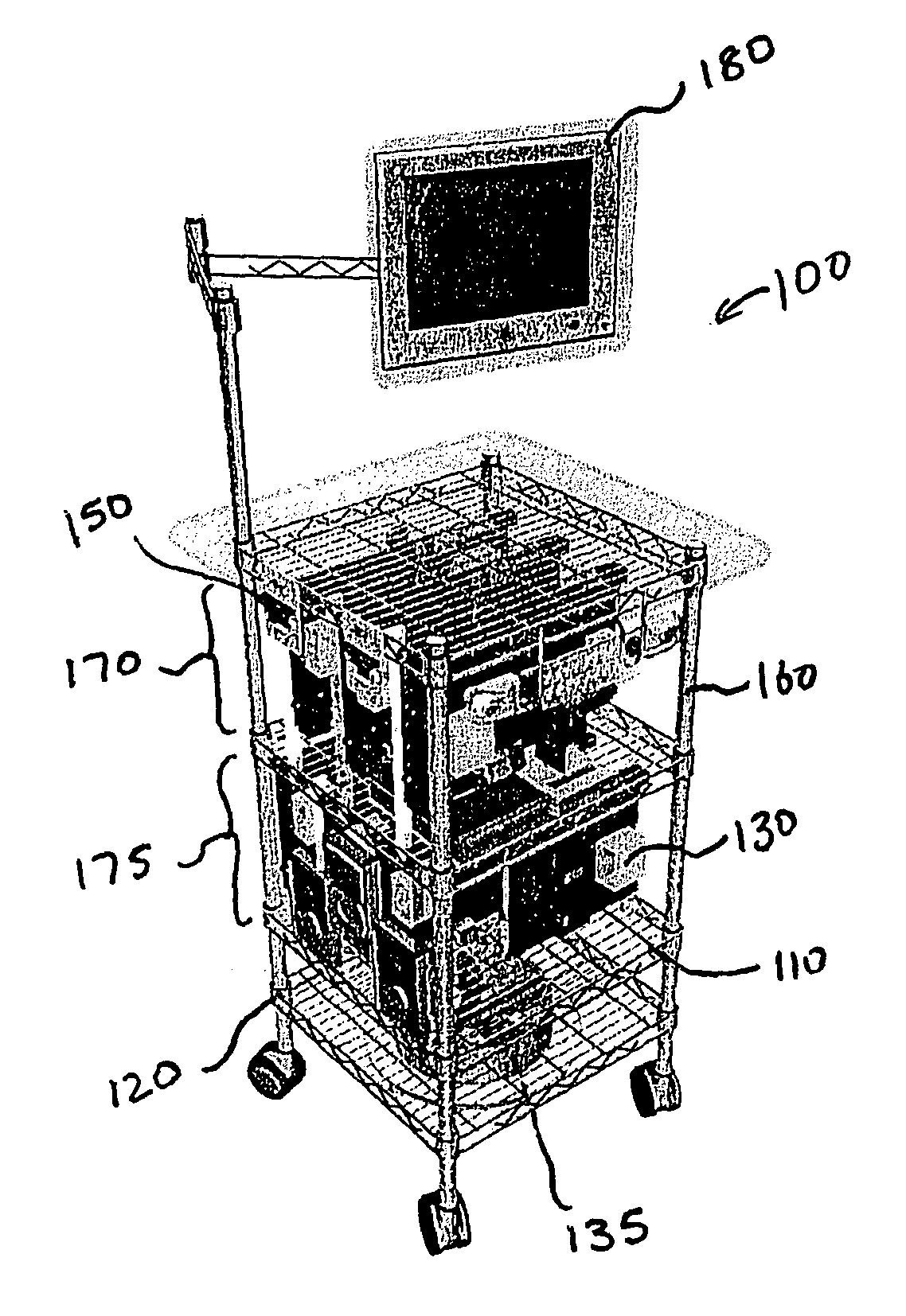
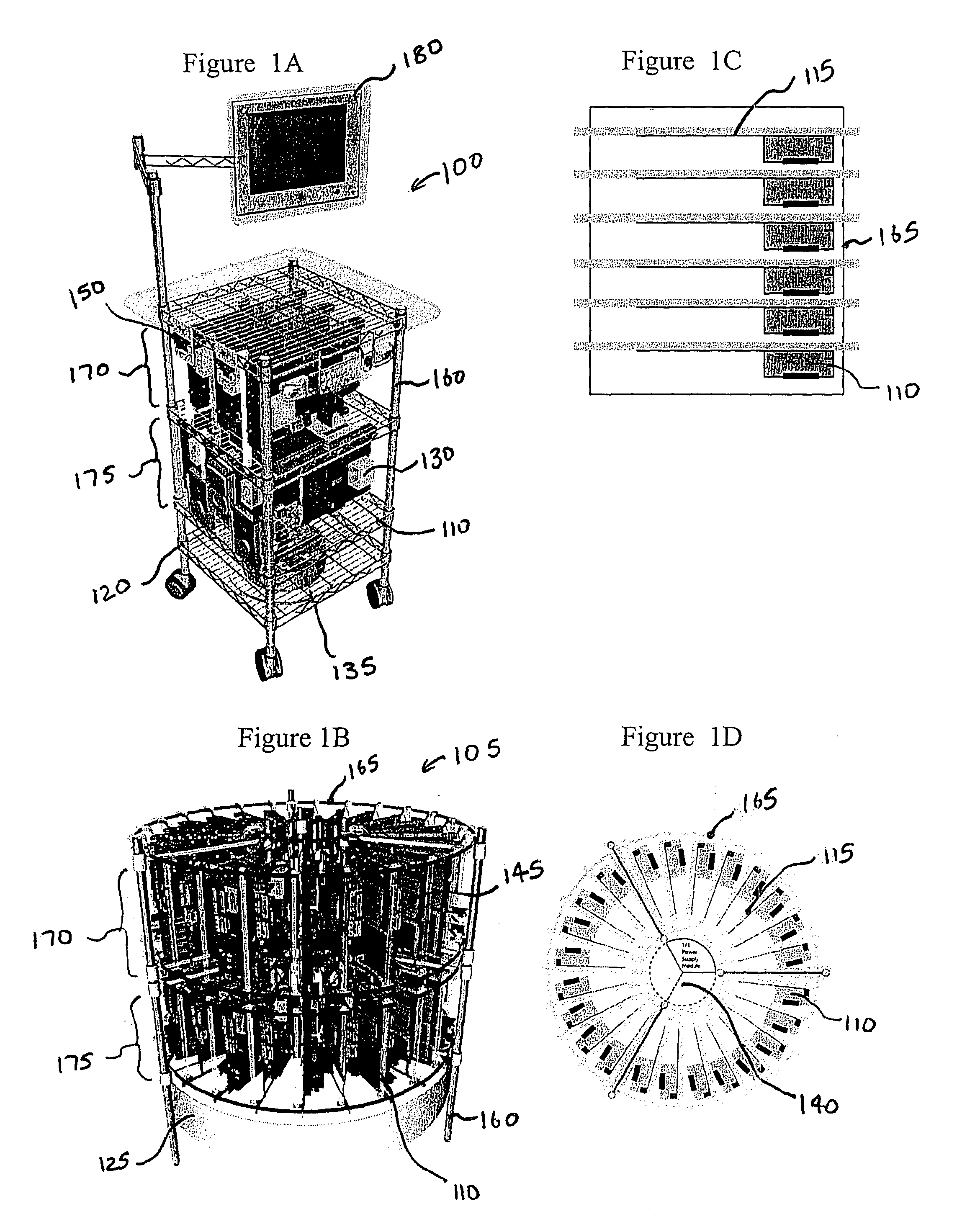
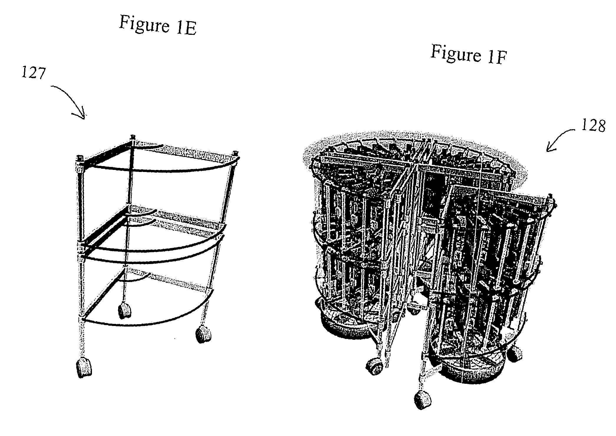
[0041]FIGS. 1A and 1B illustrates modular—or adaptable—housing assemblies 100 and 105 for housing multiple computer modules according to one embodiment. The housing assemblies 100 and 105 include several computer modules 110 coupled to a frame assembly 115, housings 120 and 125, a cooling system having cooling...


PUM


Abstract

This invention is directed towards assemblies of electrical or electronic circuit boards. More specifically, the present invention relates to an assembly for housing multiple computer circuit boards. The assembly include a housing that has several railing coupled to the housing. A connector is structurally and electrically coupled to the railings for hanging the computer circuit boards. Structural coupling between the connector and the railing is accomplished by placing the connector in contact with the railing in a file hanging method. This contact also creates an electrical coupling and establishes an electrical connection between the connector and the railing.

Description

FIELD OF INVENTION [0001] The invention relates generally to assemblies of electrical or electronic circuit boards. More specifically, the present invention relates to a housing assembly for stacking multiple computer modules. BACKGROUND OF THE INVENTION [0002] The current course of business demands more power from computer systems. This demand is often met through the creation of computer clusters, of which there are two primary types: “high availability” clusters, where more than one node is used to guarantee the continuous operability of a machine; and, “high performance” clusters, where several nodes combine efforts to yield more processing power. Such clusters require a method of organization and storage. A general method is physically housing individual computers in a single compartment. Examples of this method include housing regular tower and desktop computers on metal frames and rack-mounting computer units. [0003] The method of stacking computers on metal frames is widely ...

Claims


Application Information

Patent Timeline
IPC IPC(8): G06F1/18G06F1/20
CPCG06F1/183G06F1/20G06F1/189
Inventor ARIPPOL, DERICK
Owner ARIPPOL DERICK
Learn More