Loudspeaker coil suspension system

a technology of suspension system and loudspeaker coil, which is applied in the direction of diaphragm construction, transducer diaphragm, electromechanical transducer, etc., can solve the problems of suspension failure, speaker failure, adhesives attaching the suspension to the diaphragm can also fail,

Inactive Publication Date: 2005-02-03
HARMAN INT IND INC
View PDF8 Cites 5 Cited by
  • Summary
  • Abstract
  • Description
  • Claims
  • Application Information

AI Technical Summary

Benefits of technology

[0011] This invention provides an assembly system for a voice coil, suspension, and diaphragm. In one embodiment of the invention, a continuous layer of high temperature resistant polymer is shaped to form a suspension, a pocket adapted to-receive the voice coil and a flange adapted to couple to the diaphragm. A continuous layer of polymer may be shaped to perform several functions, such as the suspension, the former, and an attachment to the diaphragm. The coil may be inserted inside the pocket to protect the voice coil from electrical shorting as the voice coil expands or shrinks. The assembly system may also allow for the manufacture of different products via simply changing the diaphragm material. The diaphragm can then be optimized for different uses by changing materials. This may provide manufacturing flexibility by allowing various products to be assembled by the same tooling.
[0013] To further increase the high frequency energy generated by the compression driver, the diaphragm may be coupled to the bottom side of the inner flange area. Such an arrangement places the diaphragm closer to the phasing plug minimizing the space or cavity between the two items. With a smaller cavity, the resonance in the cavity increases, resulting in an increase in the high frequency energy generated by the compression driver.

Problems solved by technology

Despite best manufacturing efforts, speakers may fail due to excessive mechanical and thermal stresses.
For example, suspensions can fail due to environmental factors such as exposure to heat, UV rays or humidity.
Adhesives attaching the suspension to the diaphragm can also fail if applied improperly or if excess mechanical stress is applied to the jointing area.
Likewise, adhesives attaching the former to the diaphragm can fail.
This happens because applying adhesive between the suspension and the diaphragm, and between the former and the diaphragm, can be a delicate process and possibly misapplied.
Another way the loudspeaker might fail is due to over heating of the voice coil.
If the voice coil experiences excessive heat expansion, it may come into contact with the sidewalls of the magnetic gap.
If this condition occurs and the voice coil is not insulated, the resulting contact between the voice coil and the sidewalls can cause an electrical short circuit and terminal failure will occur.
Another shortcoming of current compression driver devices is that additional acoustic energy may not be provided in high frequency applications.
In high frequency applications, additional acoustic energy is desired from the compression driver, but with current designs such additional acoustic energy may not be provided.
With a smaller cavity, the resonance in the cavity increases, resulting in an increase in the high frequency energy generated by the compression driver.

Method used


Image

  • Loudspeaker coil suspension system
  • Loudspeaker coil suspension system
  • Loudspeaker coil suspension system

Examples


Embodiment Construction

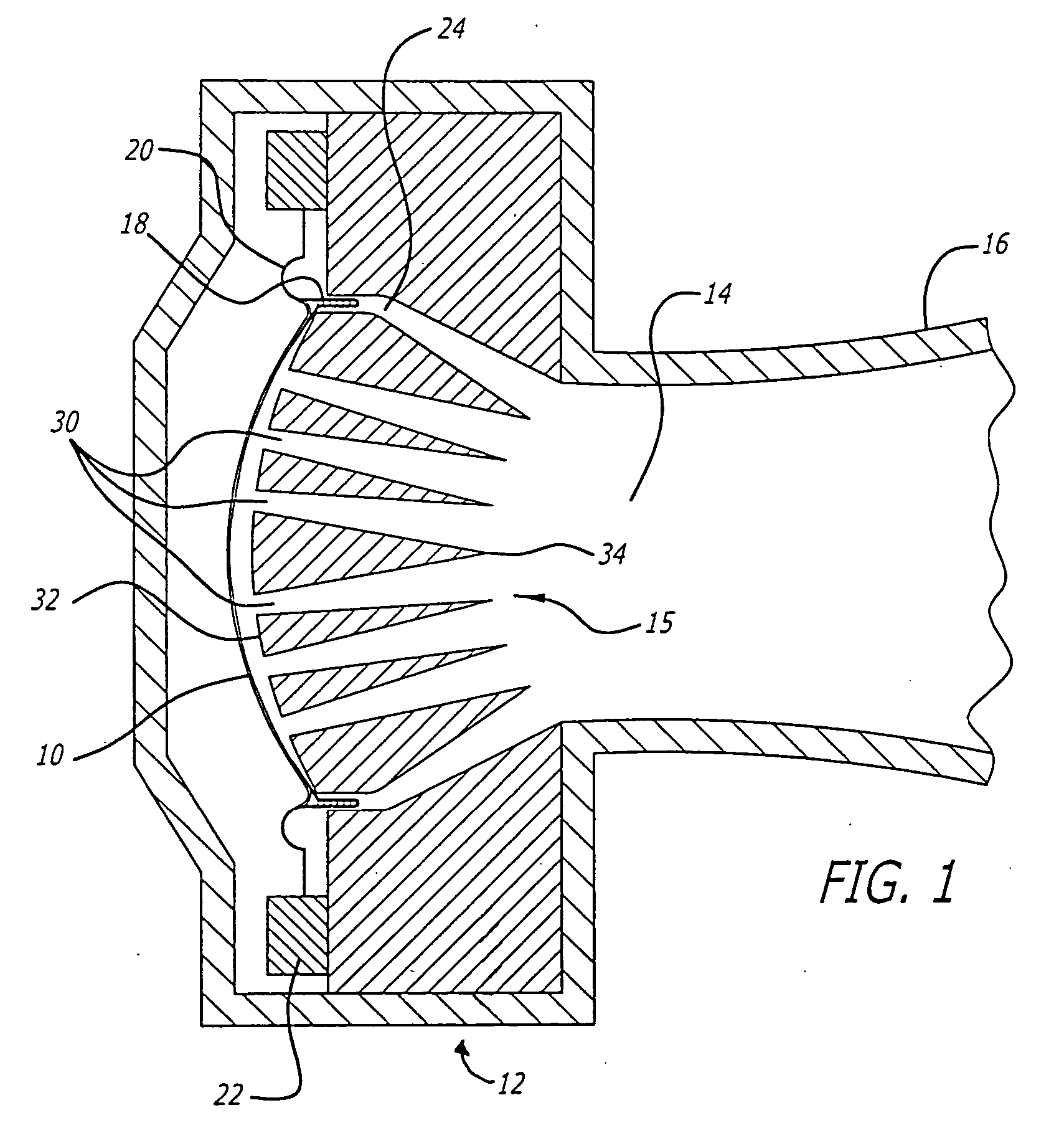
[0028]FIG. 1 illustrates a cross sectional view of a compression driver 12 coupled to the throat 14 of a horn 16. To convert the electrical energy into sound, a combination of a diaphragm 10 and a phasing plug 15 is coupled to the throat 14 of a horn 16. The phasing plug 15 may be made of ferromagnetic material that has a plurality of bores 30 between the rear side 32 and the front side 34. The coil 18 is insulated and disposed within an annular magnetic gap 24 to vibrate freely in a direction along the longitudinal direction. To suspend the diaphragm 10 adjacent to the rear side 32 of the phasing plug 15, the outer perimeter of the diaphragm 10 is coupled to a suspension 20, which in turn is attached to a mounting plate 22.

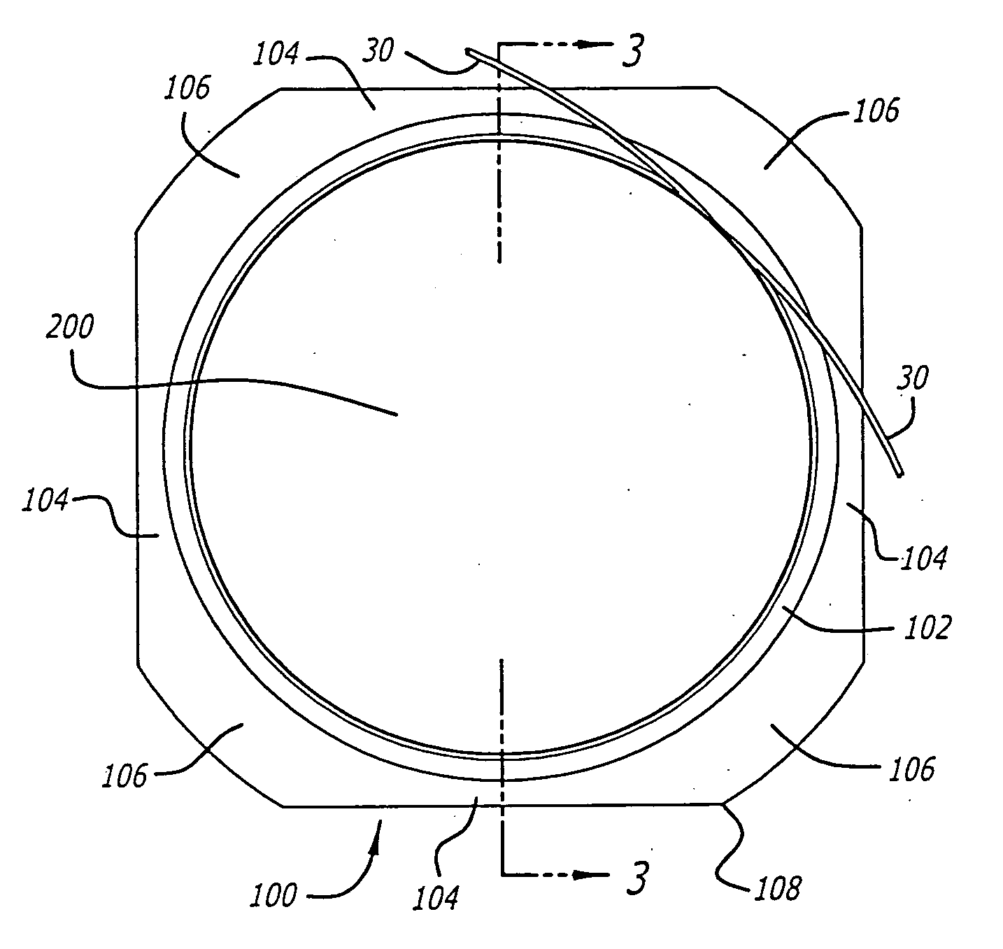
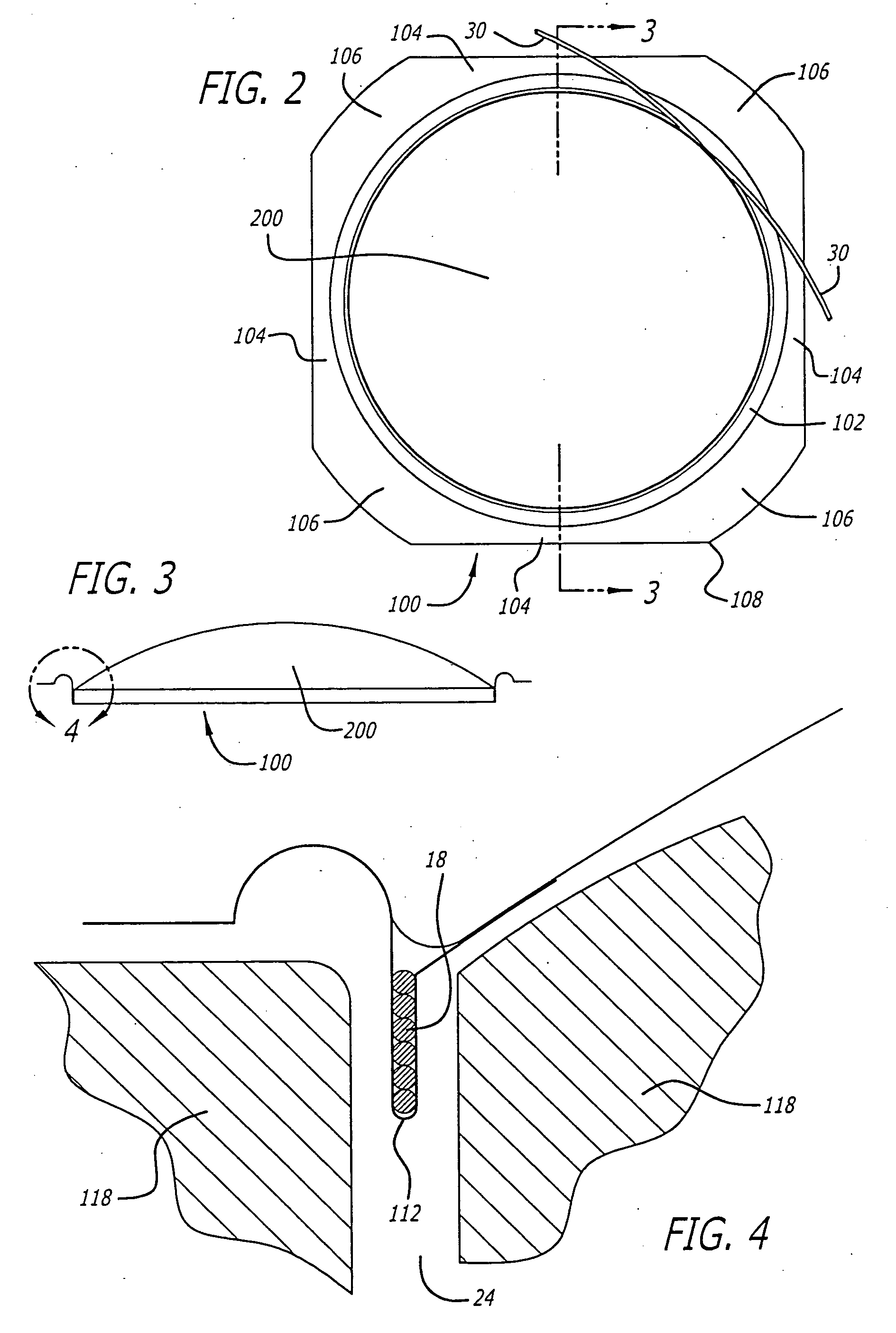
[0029]FIGS. 2-6 illustrate a unitary suspension pocket attachment (“USPA”) 100. The USPA 100 performs several functions, including: (1) acting as a suspension or compliance to accommodate the excursion of the diaphragm; (2) acting as a voice coil former; (3) att...


PUM


Abstract

The invention provides a continuous layer of polymer that is shaped to act as the suspension, the former, and an attachment to the diaphragm. The coil may be located within the pocket providing insulation to the coil thus preventing electrical short circuiting of the voice coil as the voice coil expands or contracts based on its operating temperature. The invention also provides an inner flange area of a suspension that may act as a spring generating additional acoustic energy from the compression driver. The inner flange area may also be tuned to vibrate at a predetermined high frequency. Thus, in certain applications, where more acoustic energy is desired at high frequency, the inner flange area may be tuned to provide that extra acoustic energy. To further increase the high frequency energy generated by the compression driver, the diaphragm may be coupled to the bottom side of the inner flange area. Such an arrangement places the diaphragm closer to the phasing plug to minimize the space or cavity between the two. With a smaller cavity, the resonance in the cavity increases, so that the compression driver generates more energy at high frequency.

Description

1. CROSS-REFERENCES TO RELATED APPLICATION [0001] This application is a non-provisional application claiming priority to U.S. provisional application, Ser. No. 60 / 221,693 filed Jul. 31, 2000.BACKGROUND OF THE INVENTION [0002] 2. Field of the Invention [0003] This invention relates to a loudspeaker coil suspension and dome system that acts to protect the coil from electrical shorting. [0004] 3. Related Art [0005] A loudspeaker is a device for converting variations of electric energy into corresponding variations of acoustic energy. To convert the electrical energy into sound, a combination of a diaphragm and a compression driver is coupled to the throat of a horn. The compression driver typically includes a phasing plug made of ferromagnetic material having a plurality of bores between the rear side and the front side of the phasing plug. [0006] Generally, the coil is wrapped around the exterior side of a cylindrically shaped former. The combination of the former and coil are then di...

Claims


Application Information

Patent Timeline
Patent Type & Authority Applications(United States)
IPC IPC(8): H04R7/12H04R7/20H04R9/04
CPCH04R7/127H04R9/04H04R7/20
Inventor BUTTON, DOUGLAS J.
Owner HARMAN INT IND INC
Why Eureka
Try Eureka