U-shaped float tube with stabilizing frame

Inactive Publication Date: 2005-02-03
HOWERTON LARRY
View PDF22 Cites 19 Cited by
  • Summary
  • Abstract
  • Description
  • Claims
  • Application Information

AI Technical Summary

Benefits of technology

[0019] The stabilizing frame is formed from one or several pieces of lightweight and rigid tubing, for example, stainless steel. A number of alternative assemblies for the frame are possible so long as the pieces may be easily and fixedly joined to one another and secured, as a unit, to the flotation chamber.
[0020] The presence of the stabilizing frame provides sufficient structure to the legs of the watercraft to prohibit their collapse when a person

Problems solved by technology

An inherent disadvantage of an open ended (i.e. U-shaped) flexible flotation device is the tendency of the tube ends to collapse towards each other as the occupant's weight is applied to the seat suspended between the two legs of the device.
This is in fact an inherent problem with all previous U-shaped non-rigid flotation devices.
Thus the occupants of Steel's, Alter's and Huston's devices find it difficult

Method used


Image

  • U-shaped float tube with stabilizing frame
  • U-shaped float tube with stabilizing frame
  • U-shaped float tube with stabilizing frame

Examples


Example

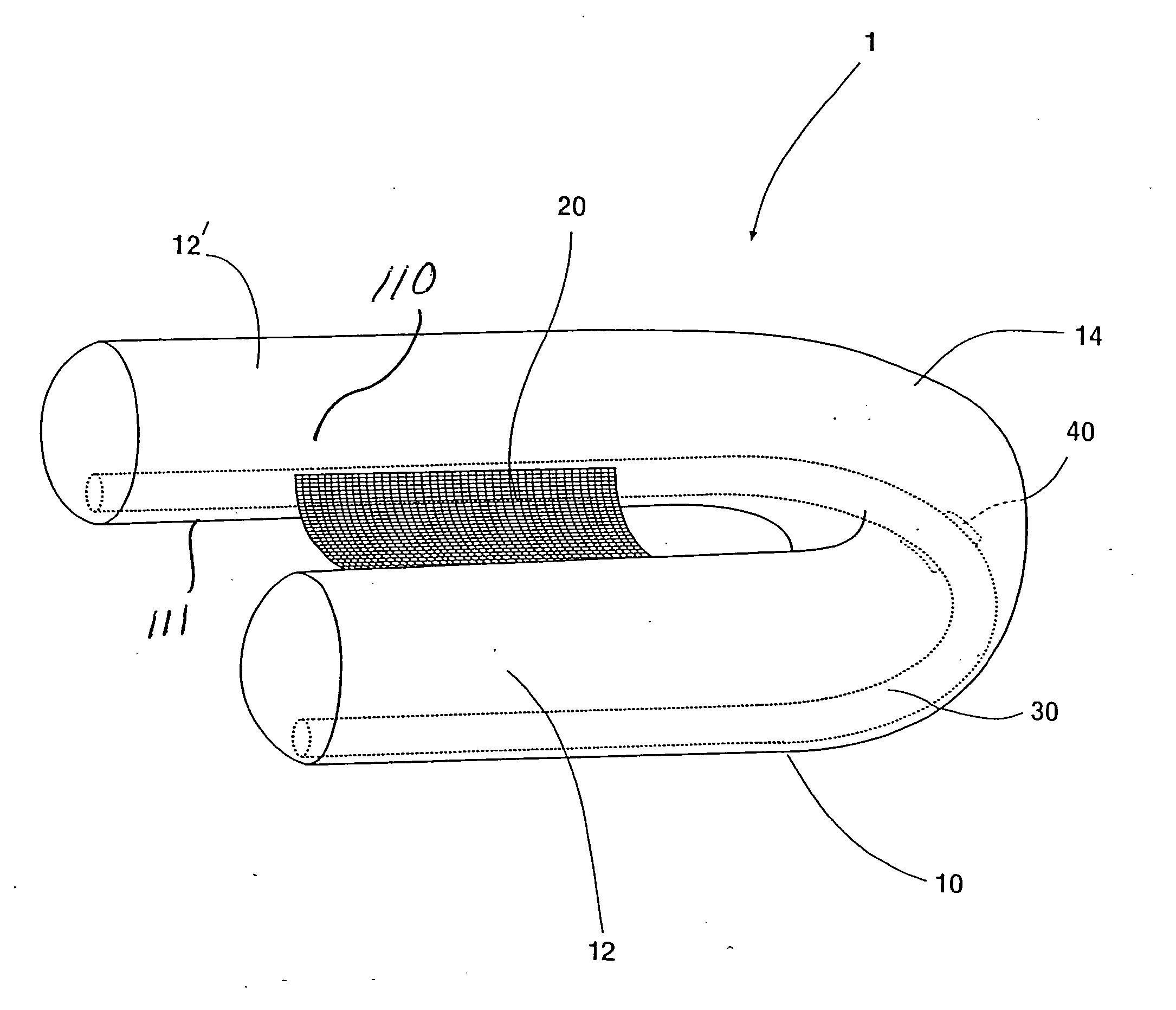
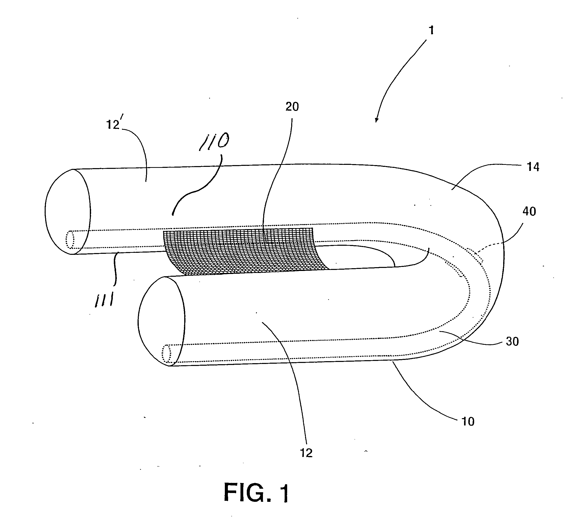
[0035]FIG. 1 depicts the invented float tube 1. Fisherman, hunters, sportsmen and the like will typically use this flotation device. This invention is generally comprised of a U-shaped inflatable flotation chamber 10 having two generally parallel and laterally disposed leg portions 12 and 12′ and a rearward portion 14. The leg portions are preferably formed integrally with the rearward portion. Preferably, a flexible seating device 20 is connected to and bridges the leg portions 12 and 12′ of the flotation chamber 10 though a rigid, or other seating device may be possible. FIG. 1 also shows in phantom an embodiment of the frame feature of this invention, the U-shaped stabilizing frame 30 and system 40 for connecting the frame to the flotation chamber 10. The latter important features are better visualized in FIG. 2.

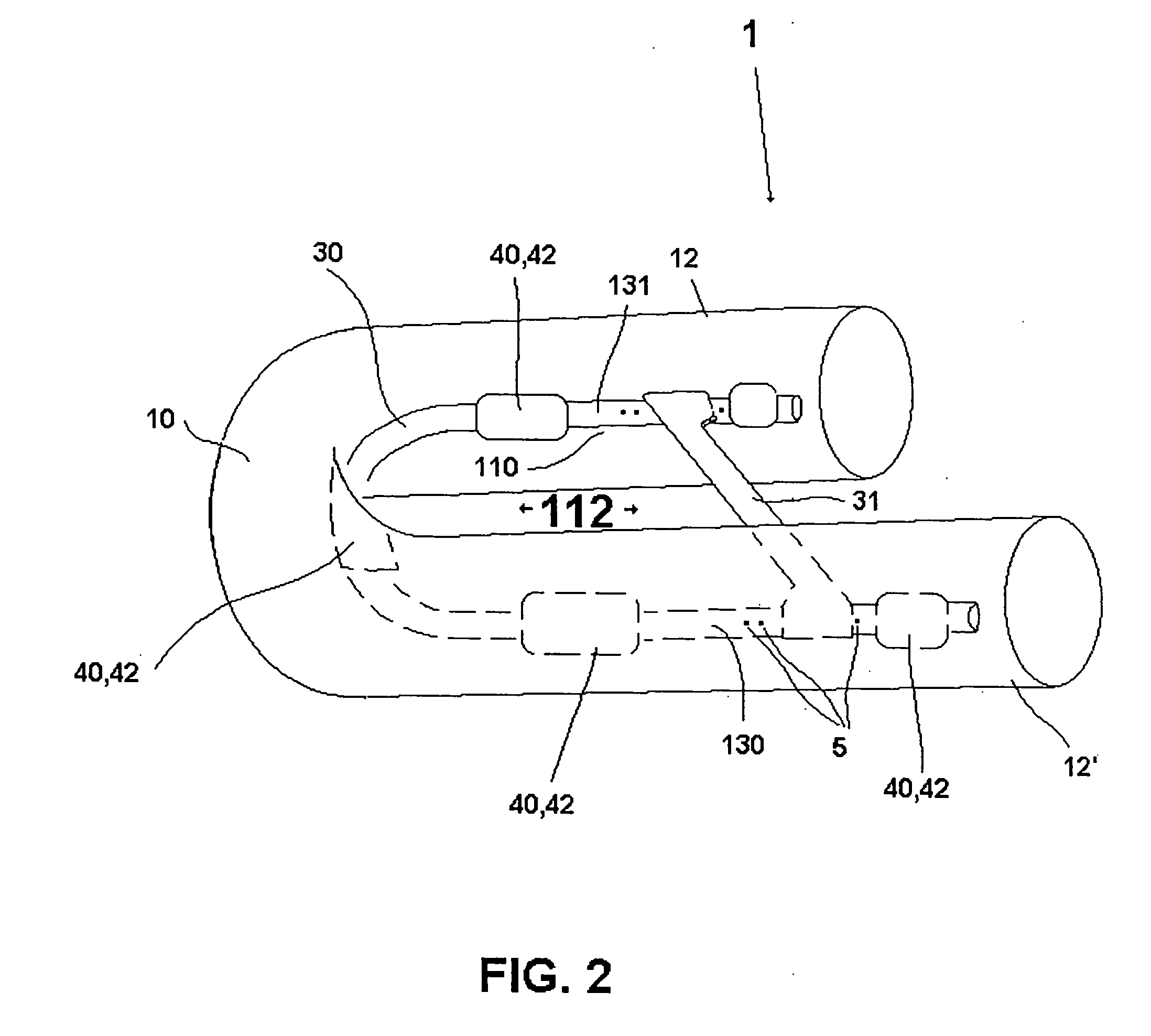
[0036]FIG. 2 shows the preferred embodiment of the invention wherein the system 40 for connecting the U-shaped stabilizing frame to the flotation chamber comprises a plu...


PUM


Abstract

A float tube or watercraft comprised of a generally U-shaped inflatable flotation chamber having two generally parallel and laterally disposed leg portions and a rearward portion. The leg portions are preferably formed integrally with the rearward portion. The invention further includes a seating device bridging the two leg portions of the flotation chamber. A stabilizing frame and system for connecting the stabilizing frame to the U-shaped flotation chamber provides support to the opposing legs of the flotation chamber and prevents them from pinching in on the occupant, and also preferably tensions a seat provided between the legs of the floatation chamber. For additional support and/or this preferred tensioning, a rigid and/or adjustable rod, or tube, extends between the opposing legs of the frame. The system for connecting the stabilizing frame comprises preferably a plurality of channel segments, which are fixedly secured to the leg and rearward portions of the flotation chamber. Alternatively, a continuous channel may be used.

Description

[0001] This application is a continuation-in-part of, and claims priority from, U.S. Non-Provisional application Ser. No. 10 / 268,134, filed on Oct. 9, 2002, issuing as U.S. Pat. No. 6,749,475, on Jun. 15, 2004, entitled “U-Shaped Float Tube With Stabilizing Frame,” the disclosure of which is incorporated herein by this reference.BACKGROUND OF THE INVENTION [0002] 1. Field of the Invention [0003] The present invention relates to personal watercraft. More specifically, this invention relates watercraft which incorporate inflatable flotation apparatus. [0004] 2. Related Art [0005] There are many personal watercraft designed to accommodate a single individual and to provide suitable buoyancy and transport for that person. The primary application of such devices is to get the “fisherman” to his / her preferred fishing location and to support that person during the fishing activity. Such craft are produced in a large variety of configurations. Many are formed in a closed configuration such ...

Claims


Application Information

Patent Timeline
IPC IPC(8): B63B35/78
CPCB63B35/78A47C15/006B63B34/52
Inventor HOWERTON, LARRY
Owner HOWERTON LARRY
Why Eureka
Try Eureka