Microserver test port retrofit kit

a microserver and retrofit kit technology, applied in the direction of instruments, transportation and packaging, wireless commuication services, etc., can solve the problems of component failure, repair or replacement, time loss, and associated costs, and achieve the effect of ensuring the integrity of the system, and ensuring the safety of the system

Inactive Publication Date: 2005-02-03
UNITED TECH CORP
View PDF5 Cites 38 Cited by
  • Summary
  • Abstract
  • Description
  • Claims
  • Application Information

AI Technical Summary

Benefits of technology

[0011] In accordance with another aspect of the disclosure, a deployed product is disclosed which may comprise a machine, an electronic control box operatively associated with the operating machinery, and a microserver connected to a PC test port of the electronic control box. The microserver may host a web page and generate a wireless system around t

Problems solved by technology

It is when a component fails and has to be repaired or replaced.
This normally occurs as an end result of its operators not understanding its component life or the conditions of its use, and the highest costs, both physical and lost time, are associated with it.
Unfortunately, it is also one of the most common types of maintenance.
Scheduled maintenance is less costly but can be very wasteful.
Without first-hand knowledge of how a product is being used after it is sold and deployed to the field, a manufacturer or service provider has no real way of knowing when components will wear out based on usage, and must therefore default back to using one or both of the first two types of maintenance described above.
Operators are in the best position to gather this first hand knowledge, but most are too busy operating and making money with the product and have little time, money and/or inclination to attempt to capture this information to provide feedback to the manufacturer or service provider, even though it is in their own best interest to do so.
This is a highly manual and painful method of collecting operational in

Method used


Image

  • Microserver test port retrofit kit
  • Microserver test port retrofit kit
  • Microserver test port retrofit kit

Examples


Embodiment Construction

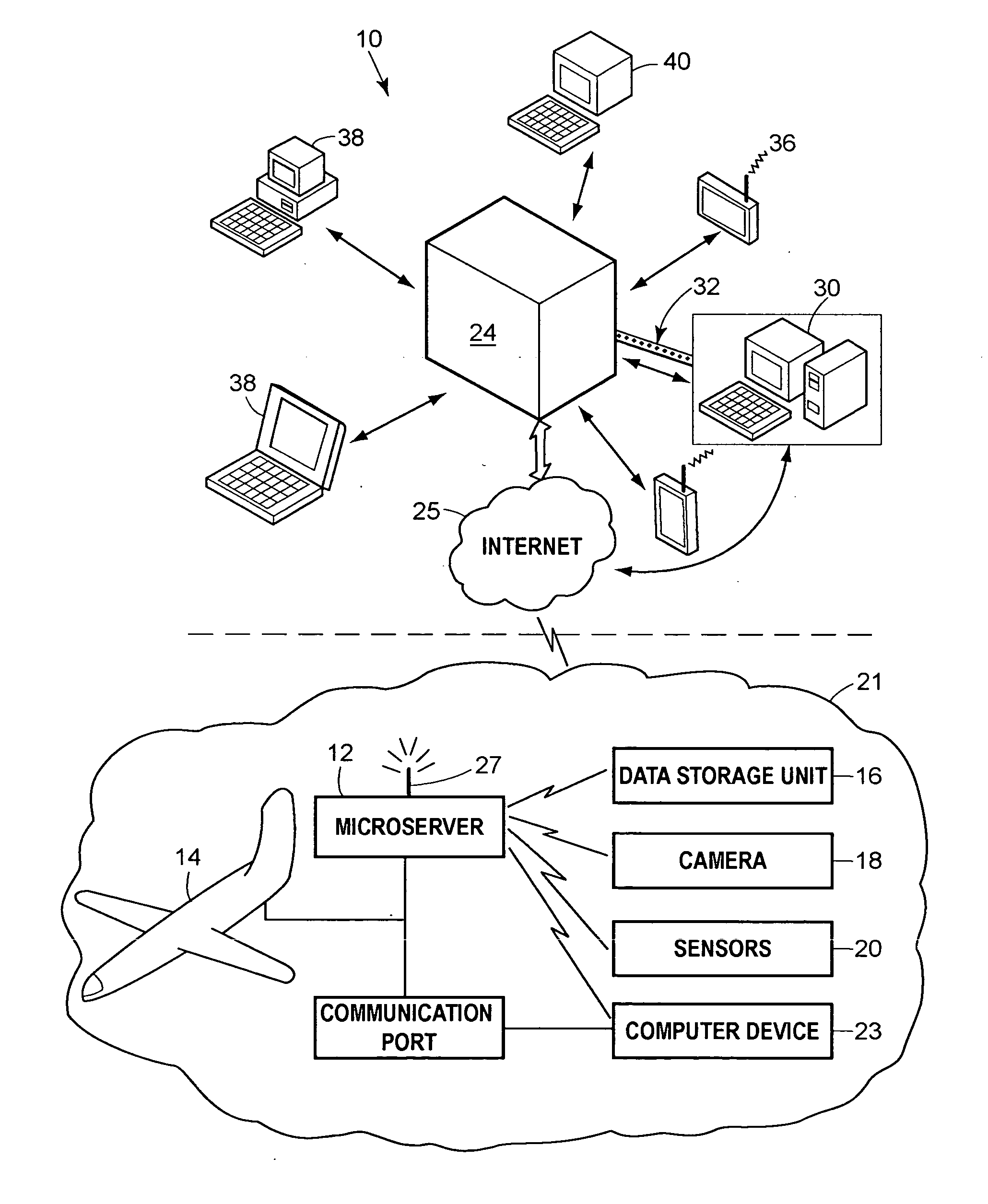
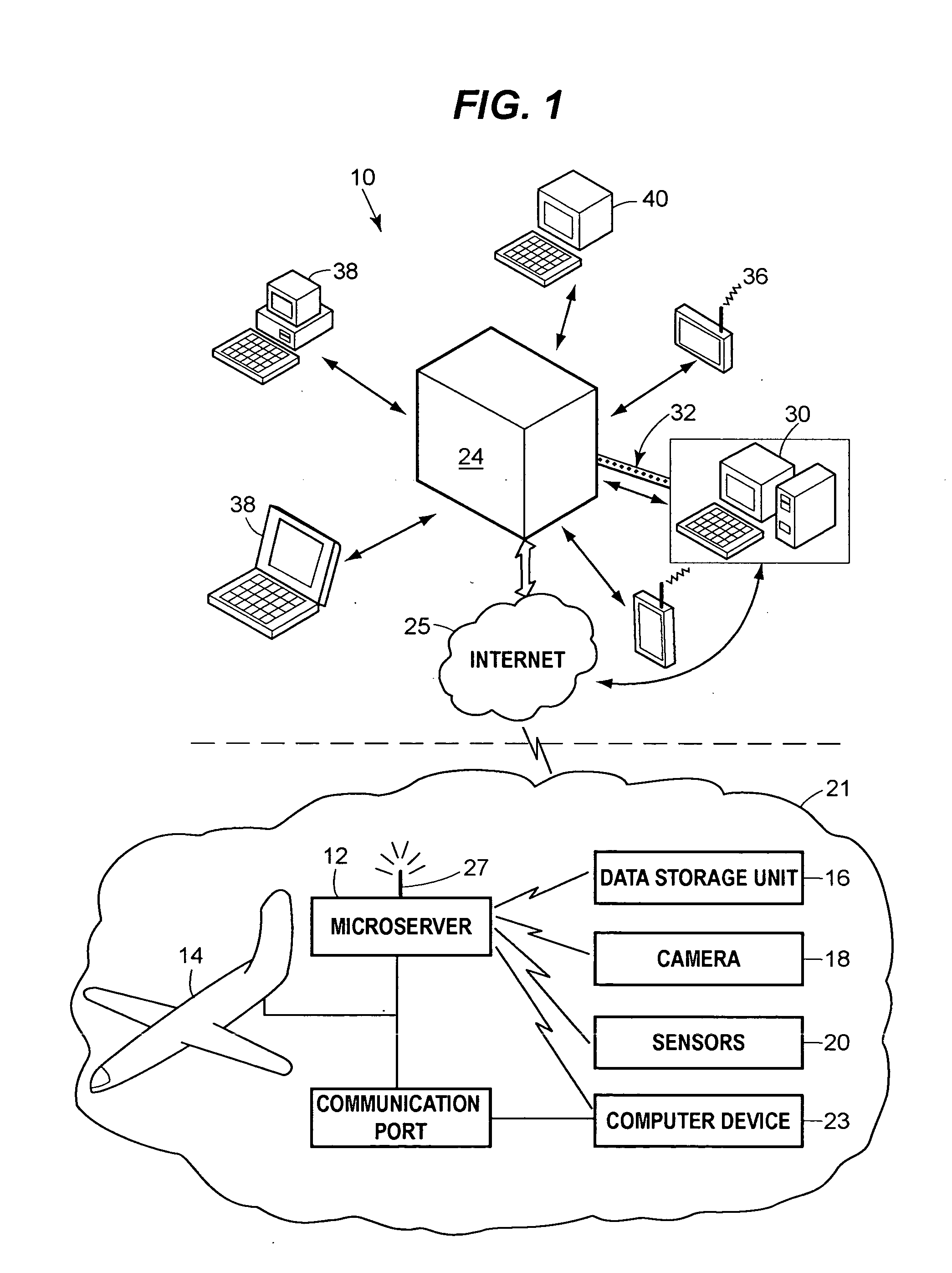
[0019] Referring now to FIG. 1, a system 10 is presented which is capable of monitoring a deployed product, gathering data about the deployed product, and disseminating the data to interested parties. It is also capable of monitoring and restricting access to its data, and can accept data for storage or integration within the product itself, such as firmware revision updates. As used herein, the term “deployed product” has broad applicability and refers to any product, component, or system on a variety of machines including, but not limited to, a vehicle, a HVAC system, or an elevator / escalator system, such as a propulsion system on a vehicle, a compartment of a vehicle, or a braking system for a vehicle, wherein the vehicle is any one of a number of movable devices including aircraft and elevator cars.

[0020] The system 10 includes a server 12 located on the deployed product or movable platform 14. The movable platform 14 may be a boat, an airplane, a spacecraft, an automobile, a t...


PUM


Abstract

An integrated system for monitoring a deployed product on a movable platform, gathering data about the deployed product, and disseminating the data about the deployed product is disclosed. The system includes a server located on the movable platform capable of communication with the server from a remote location. The server communicates with a source of data about the deployed communicates with a source of data about the deployed product. The system further includes a portal onto which data gathered by the server may be downloaded and with which one can upload information to the server. The server may be connected to an existing PC test port of a controller pre-existing onboard the deployed product to easily retrofit existing machines to be web-enabled.

Description

CROSS-REFERENCE TO THE RELATED APPLICATION [0001] This is a continuation-in-part of U.S. patent application Ser. No. 10 / 155,593, filed on May 22, 2002, which claims priority to U.S. provisional patent application Ser. No. 60 / 337,926, filed on Dec. 3, 2001, both of which are herein incorporated by reference.FIELD OF THE DISCLOSURE [0002] The present disclosure generally relates to integrated Internet systems and, more particularly, relates to the provision of an Internet portal on board a deployed product. BACKGROUND OF THE DISCLOSURE [0003] There are three general types of maintenance for products. They are on-demand maintenance (usually when a product breaks), scheduled maintenance (based upon the best estimate of a manufacturer as to when something will wear out with normal usage), and condition based maintenance (maintenance that occurs when maximum usage is obtained from a part but just prior to part failure). On demand maintenance is self-explanatory. It is when a component fai...

Claims


Application Information

Patent Timeline
IPC IPC(8): G06Q50/00B64F5/00G06F13/00G06Q10/00H04L12/28H04L29/06H04L29/08
CPCG06Q10/06H04M3/301H04W4/00H04L69/329H04L67/04H04L67/12H04L67/02H04L67/025
Inventor LODA, DAVID C.KENNEDY, CAMPBELLPAQUET, MICHEL D.DOLAN, WILLIAM J.POISSON, RICHARD A.STICKLING, BJORNMACCHIA, ENZOQADRI, SAMAD
Owner UNITED TECH CORP
Why Eureka
Try Eureka