Waste disposal devices

a technology of waste disposal and waste packaging, which is applied in the field of waste disposal devices, can solve the problems of knotting of waste packages, affecting the appearance of waste packaging, and the inability to remove waste packages, etc., and achieves the effect of convenient and expedient manner

Inactive Publication Date: 2005-02-10
MUNCHKIN INC
View PDF41 Cites 35 Cited by
  • Summary
  • Abstract
  • Description
  • Claims
  • Application Information

AI Technical Summary

Benefits of technology

[0022] It is yet another object of the present invention to provide new and improved waste disposal devices in which a series of encapsulated waste packages are formed and can be removed from the device in an easy and expeditious manner.
[0023] It is another object of the present invention to provide new and improved diaper pails which alleviate a problem in known diaper pails, namely the need ...

Problems solved by technology

A twist rim is rotatably coupled to the cartridge such that rotation of the twist rim causes twisting of the tubing.
A major inconvenience of diaper pails of the “Diaper Genie”™ type is that it is necessary to manually tie both ends of the tubing to use the diaper pail.
The necessary, multiple tyings of the tubing is bothersome and moreover, when the knots are not made sufficiently strong, unpleasant odors emanating from the waste packages can escape through the knots.
Another problem with diaper pails of the “Diaper Genie”™ type is that cutting the tubing is difficult and requires the use of a manually operable cutting instrument.
This cutting instrument does not enable easy cutting of the tubing.
Yet another problem with diaper pails of the “Diaper Genie ”™ type is that the series of waste packages are removed from the diaper pail through an access door pivotally connected to the bottom end of the container.
The series of...

Method used


Image

  • Waste disposal devices
  • Waste disposal devices
  • Waste disposal devices

Examples


Embodiment Construction

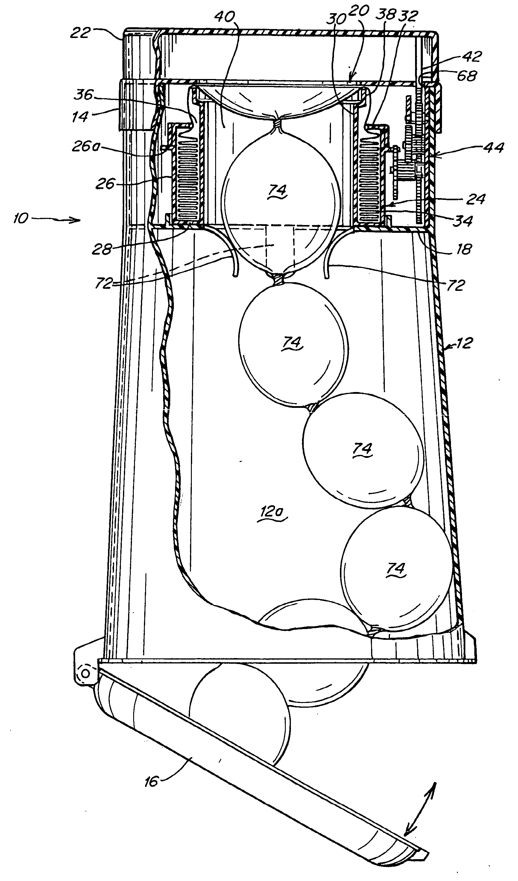
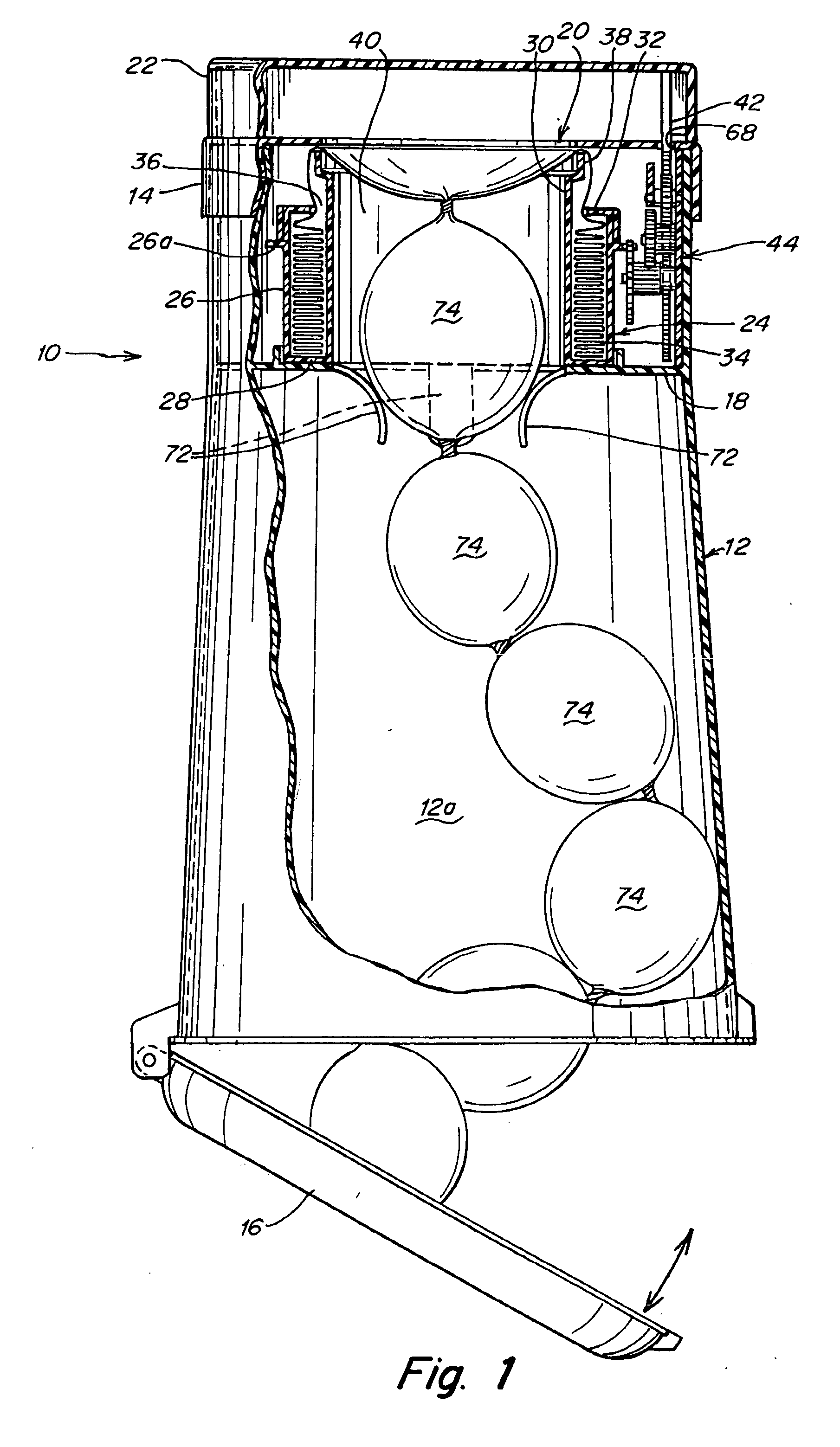
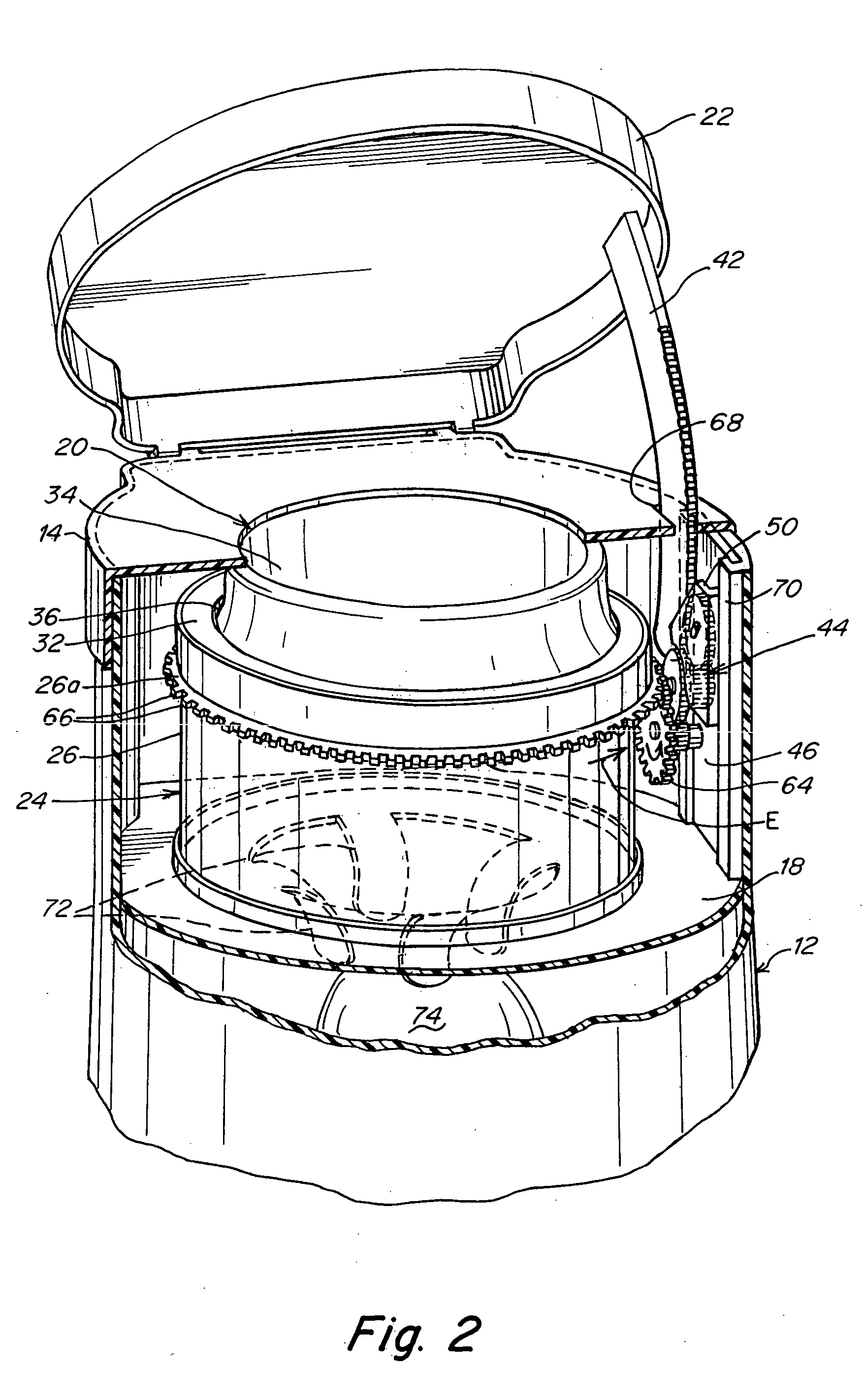
[0090] Several embodiments of waste disposal devices in accordance with the invention are described below. Generally, the waste disposal devices provide for relative rotation between a cartridge of flexible tubing and a retention unit, mechanism or member which holds a waste package stationary, i.e., either the cartridge is rotated relative to the retention unit or the retention unit is rotated while the cartridge is stationary. In this manner, the flexible tubing is caused to twist above the waste package thereby encapsulating the waste package in the tubing. The encapsulated waste package is then urged into a waste receiving chamber of the waste disposal device upon the insertion of another waste package into the device to be encapsulated or in some embodiments, provisions are made to enable the encapsulated waste package to be drawn into the waste receiving chamber without dependency on the subsequent insertion of another waste package. Repeated insertions of waste packages cause...


PUM

PropertyMeasurementUnit
Flexibilityaaaaaaaaaa
Melting pointaaaaaaaaaa
Circumferenceaaaaaaaaaa

Abstract

Waste disposal device including a container defining a waste-receiving chamber, an insert defining a cavity receivable of a pack of flexible tubing for encapsulating waste packages and an inner lid connected to the container and selectively substantially covering or exposing an open top of the insert leading to the cavity. The inner lid and insert define a dispensing opening through which the tubing passes during use of the waste disposal device. An outer lid, optionally pivotally connected to the container, is movable between a position in which the waste-receiving chamber is accessible and a position in which the waste-receiving chamber is covered. A retention mechanism holds the waste package while a rotation mechanism causes rotation of the retention mechanism relative to the insert to cause a twist to be formed above a waste package when held by the retention mechanism and thereby encapsulate the waste package in the tubing.

Description

CROSS-REFERENCE TO RELATED APPLICATIONS [0001] This application is a continuation-in-part of application Ser. No. 10 / 693,087 filed Oct. 23, 2003 which is a continuation of application Ser. No. 10 / 456,428 filed Jun. 6, 2003, which is a continuation of application Ser. No. 10 / 138,058 filed May 2, 2002, now U.S. Pat. No. 6,612,099 issued Sep. 2, 2003, which claims priority under 35 U.S.C. §119(e) of U.S. provisional application Ser. No. 60 / 288,186 filed May 2, 2001, U.S. provisional patent application Ser. No. 60 / 337,355 filed Nov. 8, 2001 and U.S. provisional patent application Ser. No. 60 / 359,148 filed Feb. 20, 2002, the contents of all of which are incorporated herein by reference.FIELD OF THE INVENTION [0002] The present invention relates generally to waste disposal devices using packs of flexible tubing, and more particularly, to improved health care apparatus for the sanitary and odorless packaging and disposal of diapers and similar or related waste, medical waste, industrial wa...

Claims


Application Information

Patent Timeline
IPC IPC(8): B65B9/15B65B67/12B65F1/06B65F1/10B65F1/12B65F1/14
CPCB65B9/15B65B67/1277B65F1/062B65F2240/132B65F1/1426B65F2210/1675B65F2230/15B65F1/12
Inventor STRAVITZ, DAVID M.
Owner MUNCHKIN INC
Why Eureka
Try Eureka