Roebel bar for an electrical machine and method for producing such a roebel bar

Inactive Publication Date: 2005-02-10
ALSTOM TECH LTD
View PDF11 Cites 15 Cited by
  • Summary
  • Abstract
  • Description
  • Claims
  • Application Information

AI Technical Summary

Benefits of technology

It is therefore the object of the invention to provide a Roebel bar which avoids the enumerated disadvantages of known bars and is distinguished in part

Problems solved by technology

The offset edges of the tape (overlapping points) produce dielectric inhomogeneities, which lead to highly excessive field intensities, specifically in the region of the bar edges (where the background electric field is in any case already about twice as high as on the wide sides).
The materials used (electrically conducting mastic, but

Method used


Image

  • Roebel bar for an electrical machine and method for producing such a roebel bar
  • Roebel bar for an electrical machine and method for producing such a roebel bar
  • Roebel bar for an electrical machine and method for producing such a roebel bar

Examples


Example

WAYS OF IMPLEMENTING THE INVENTION

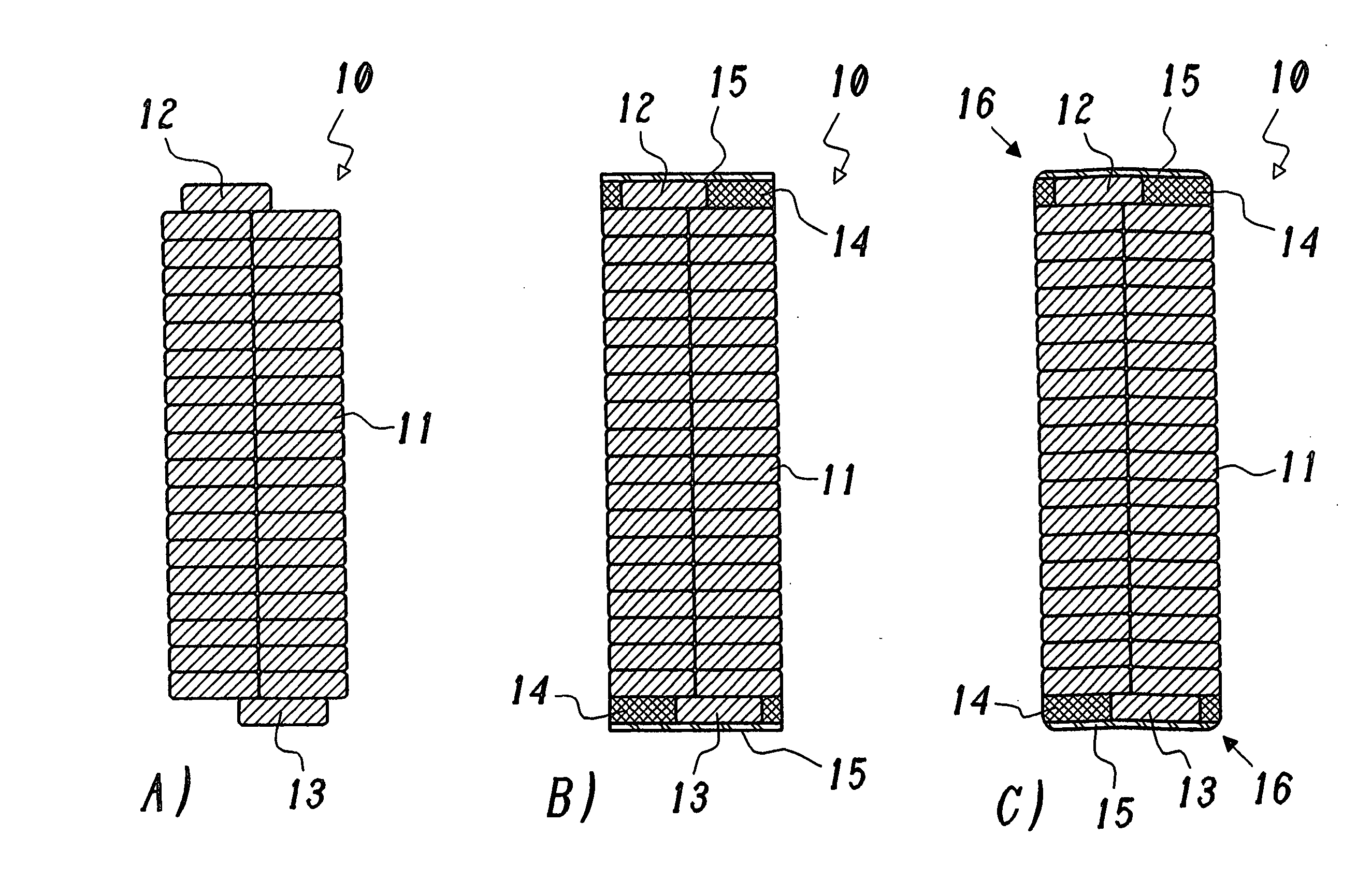
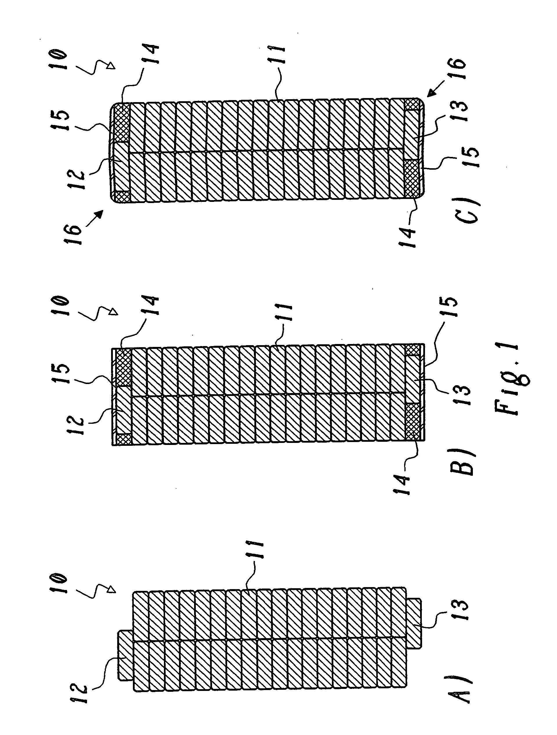
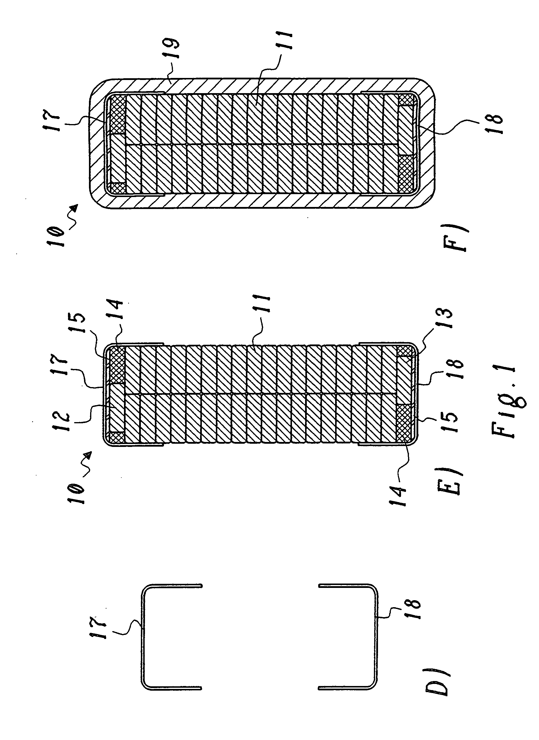
In FIG. 1, various steps in the production of a Roebel bar according to a first preferred exemplary embodiment of the invention are shown in several subfigures 1A to 1F in a cross-sectional representation. Taken as a basis is a Roebel bar 10, which is formed by a multiplicity of conductor elements 11, 12 and 13, which are transposed in the customary way for Roebel transposition. The transposition is evident from the conductor elements 12 and 13 running outside the two conductor element stacks on the upper and lower narrow sides of the Roebel bar 10 (FIG. 1A).

The irregularities on the narrow sides of the bar produced by the Roebel transposition are then evened out—as described in the initially cited EP-A1-0 774 823—according to FIG. 1B by hot pressing by means of electrically conducting mastic 14 and conductive strips 15 placed over it. The filling material “ERKITT” of the Krempel company can be used for example as the electrically conducting mas...


PUM


Abstract

A Roebel bar (10) for an electrical machine comprises a plurality of essentially parallel, transposed conductor elements (11, 12, 13), which, lying over and/or next to one another, form a bar with an essentially rectangular cross section, which is surrounded on the outside by an insulation (19) and has between the insulation (19) and the conductor elements (11, 12, 13) means (14, 14′; 15, 15′; 17, 18) for forming an inner corona protection (ICP).
In the case of such a Roebel bar, particularly effective inner corona protection is achieved by the fact that the means for inner corona protection comprise preformed, angled profiles (17, 18) of an electrically conducting material, which, running in the longitudinal direction of the Roebel bar (10), enclose the edges of the bar formed by the conductor elements (11, 12, 13), and to which the insulation (19) is applied.

Description

TECHNICAL FIELD The present invention relates to the field of electrical machines. It concerns a Roebel bar for an electrical machine according to the preamble of claim 1 and a method for producing such a Roebel bar. PRIOR ART Such a Roebel bar is known for example from EP-A1-0 774 823 and U.S. Pat. No. 5,760,516. The stator windings of large electrical machines comprise winding bars which are placed in slots, are constructed from a multiplicity of parallel conductor elements and have an essentially rectangular cross section, the narrow sides of which form the upper side and underside of the bar. The individual conductor elements of the winding bars are transposed in a special way, i.e. they exchange places within the bar over the length of the bar, to suppress currents of the conductor elements. Such winding bars have long been known by the term “Roebel bars”. Owing to the dielectric inhomogeneity on the narrow bar side of Roebel bars, it is necessary in the case of relatively ...

Claims


Application Information

Patent Timeline
IPC IPC(8): H02K3/14H02K3/40H02K15/04
CPCH02K3/14H02K15/04H02K3/40
Inventor BAUMANN, THOMASKLEE, PETER
Owner ALSTOM TECH LTD
Why Eureka
Try Eureka