Core of rotation apparatus, method for manufacturing core, and rotation apparatus

a technology of rotation apparatus and core, which is applied in the direction of magnetic circuit rotating parts, magnetic circuit shape/form/construction, magnetic bodies, etc., can solve the problems of increasing cogging torque, increasing vibration of rotation apparatus, etc., and achieving the effect of reducing vibration

Inactive Publication Date: 2005-02-10
DENSO CORP
View PDF8 Cites 18 Cited by
  • Summary
  • Abstract
  • Description
  • Claims
  • Application Information

AI Technical Summary

Benefits of technology

[0011] Accordingly, it is an objective of the present invention to provide a core of a rotation apparatus, a method for manufacturing the core, and a rotational apparatus that reduce vibration.

Problems solved by technology

However, if each distance W1 is widened, the cogging torque is also increased, and thus the vibration of the rotation apparatus is increased.
Therefore, the vibration of the rotation apparatus is increased and the performance of the apparatus deteriorates.
This complicates the production control.
This makes the magnetic forces acting on the teeth uneven and thus causes the motor to vibrate.

Method used


Image

  • Core of rotation apparatus, method for manufacturing core, and rotation apparatus
  • Core of rotation apparatus, method for manufacturing core, and rotation apparatus
  • Core of rotation apparatus, method for manufacturing core, and rotation apparatus

Examples


first embodiment

[0092] A six-pole eight-slot direct-current motor 31 according to the present invention will now described with reference to the drawings.

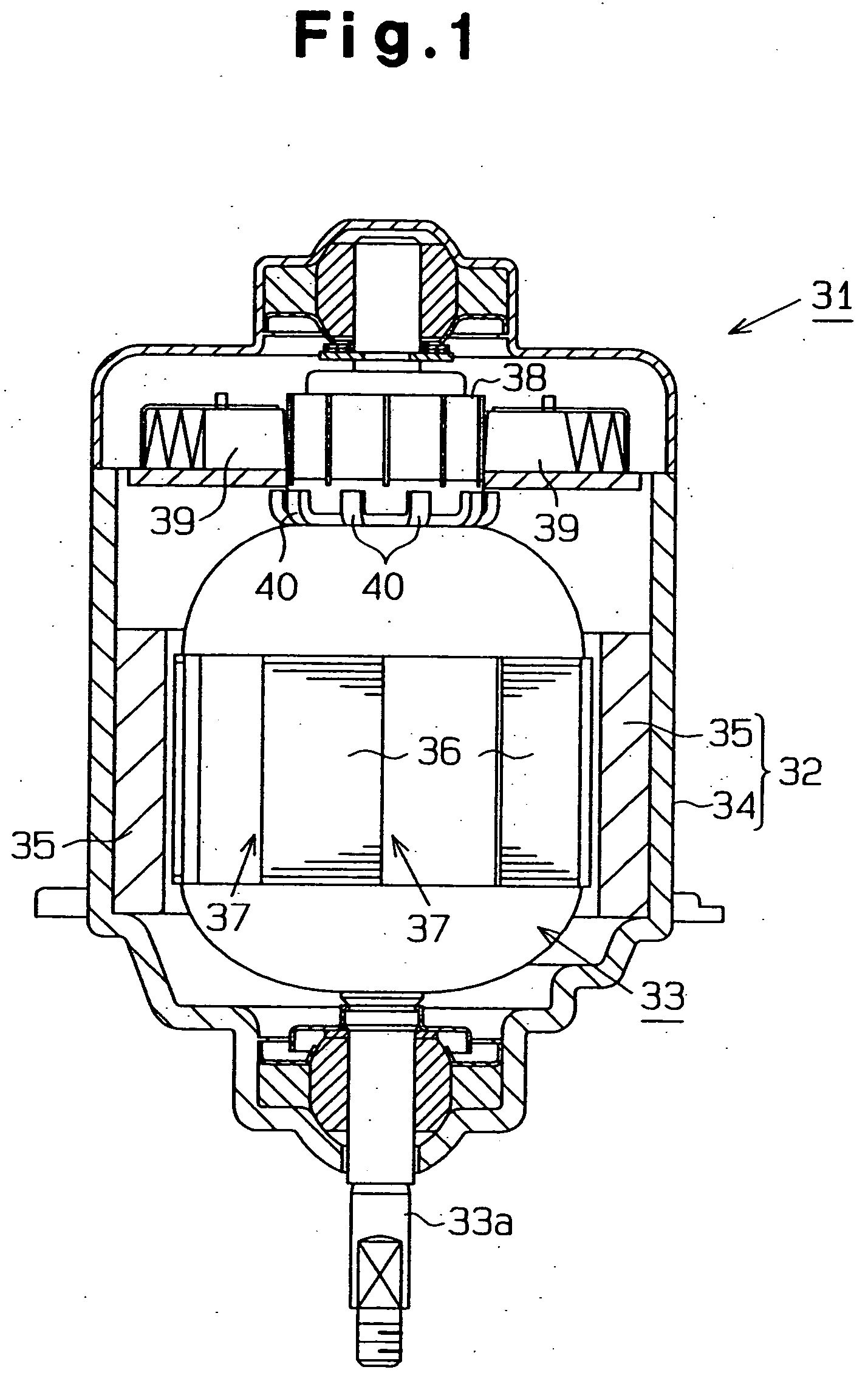
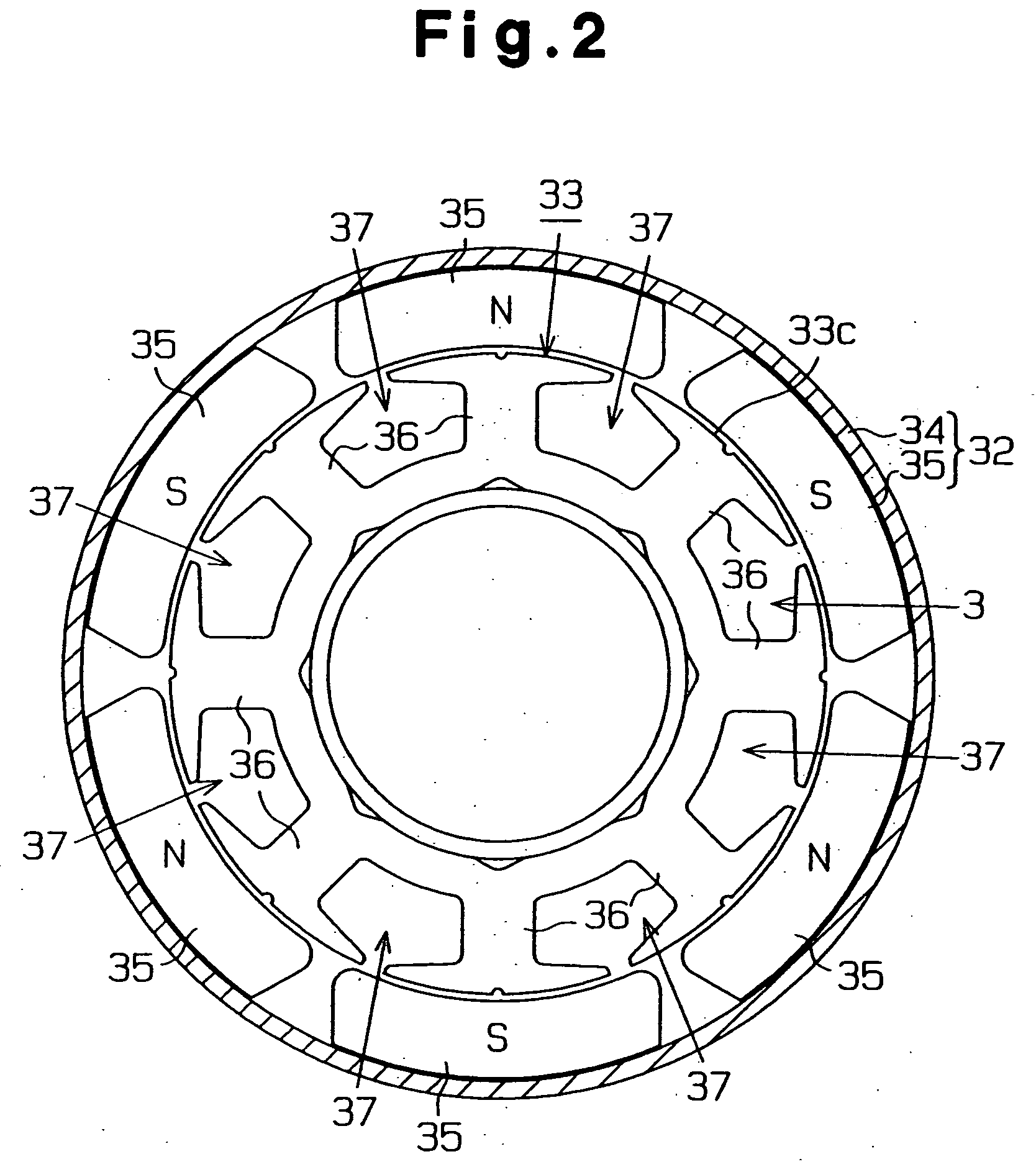
[0093] As shown in FIG. 1, the direct-current motor 31, which is a rotation apparatus, includes a stator 32 and a rotor, which is an armature 33 in this embodiment. The stator 32 includes a yoke 34 and six magnets 35, which are arranged at equal angular intervals on the inner surface of the yoke 34. Each magnet 35 functions as a magnetic pole.

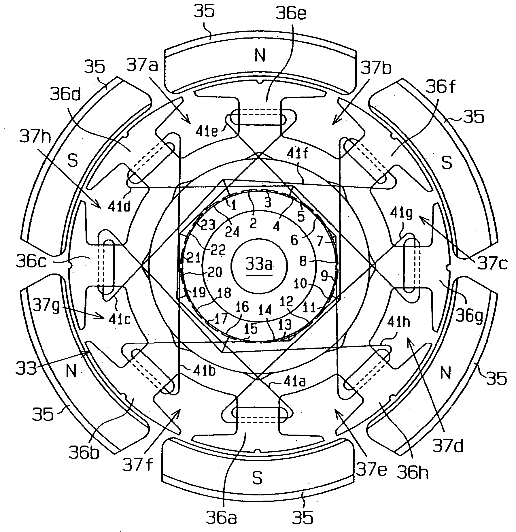
[0094] As shown in FIG. 2, the armature 33 includes a core 33c. The core 33c has eight teeth 36, which are arranged at equal angular intervals. A slot 37 is defined between each adjacent pair of the teeth 36. In FIG. 3, signs 36a, 36b, 36c, 36d, 36e, 36f, 36g, 36h are assigned to the teeth 36, and signs 37a, 37b, 37c, 37d, 37e, 37f, 37g, 37h are assigned to the slots 37.

[0095] As shown in FIG. 1, a commutator 38 is located at one end of the armature 33 to contact six brushes 39. The commutator 38 includes t...

second embodiment

[0107] In the second embodiment, the number of magnetic poles is denoted by 2m (m is an integer equal to or greater than one), and the number of the teeth of the armature is denoted by n (n is an integer equal to or greater than three). The magnets, the number of which is denoted by 2m, is arranged at every 360 / 2m degrees such that north poles and south poles are alternately arranged. The teeth, the number of which is denoted by n, are arranged at every 350 / n degrees. To function as a direct-current motor, the number 2m of the poles and the number n of the teeth need to satisfy the following formula (A).

0mn (n≠2m)  (A)

[0108] In the second embodiment, the coil is wound about the armature in short pitches. In relation with the number 2m of the poles and the number n of the teeth, the short-pitch factor K satisfies the following formula (B). The short-pitch factor K is determined by considering the space between each adjacent pair of the coils relative to the pitches between the magnet...

third embodiment

[0141] A third embodiment will now be described.

[0142] As shown in FIGS. 38 and 39, the core 50 functions as a rotor and includes a first core piece 51 and a second core piece 52, which are engaged with each other. The first core pieces 51, 52 have the same structure. Specifically, each of the core pieces 51, 52 includes a ring 53 having a center hole 53a and integral tooth members 54, the number of which is four in this embodiment. The tooth members 54 are integrally formed with the ring 53 and arranged at equal angular intervals (ninety degrees). The tooth members 54 extend radially outward from the ring 53. Also, each of the core pieces 51, 52 includes separate tooth members 55, the number of which is four in this embodiment. Each separate tooth member 55 is located on one of the integral tooth members 54. Each integral tooth member 54 has a coil winding section 54a and a distal section 54b, which is formed at the distal end of the coil winding section 54a. The ring 53 and the in...


PUM

PropertyMeasurementUnit
angleaaaaaaaaaa
angleaaaaaaaaaa
angleaaaaaaaaaa

Abstract

A motor includes a stator having magnets, a rotor having teeth, a commutator secured to the rotor, and brushes. A coil is wound about each tooth. The commutator is connected to the coils. The brushes slidably contact the commutator. The number of the magnets and the number of the teeth are determined such that the resultant of torque vectors that act on the teeth is zero. For example, the number of the magnet is six, and the number of the teeth is eight. As a result, the rotor is prevented from vibrating.

Description

BACKGROUND OF THE INVENTION [0001] The present invention relates to a core of a rotation apparatus, a method for manufacturing the core, and a rotational apparatus that reduce vibration. [0002] Japanese Laid-Open Patent Publication No. 55-147964 discloses a direct-current motor that includes magnets, an armature having a core, and a commutator. The number of the magnets is represented by a product 2 mn. The number of the teeth in the core of the armature is represented by a product m(2n±1). The number of the segments in the commutator is represented by a product mn(2n±1). In the products listed above, the sign m is an integer that is equal to or greater than one, and the sign n is an integer that is equal to or greater than three. When m is one and n is three, the number of magnet is six, the number of the teeth is seven or five, and the number of the segments is twenty-one or fifteen. [0003] Since the motor has an odd number of teeth, the resultant of magnetic forces acting on the ...

Claims


Application Information

Patent Timeline
Patent Type & Authority Applications(United States)
IPC IPC(8): H02K1/24H02K13/04H02K23/04H02K29/03
CPCH02K1/24H02K13/04H02K23/04H02K29/03Y10T29/49071Y10T29/49012Y10T29/49073Y10T29/49009Y10T29/49011
Inventor EGAWA, KANAMEYAMAMOTO, TOSHIOUEMURA, KEIICHITOYAMA, YASUHIROSANTO, SHINJITAKABE, YOSHIYUKINAKAYAMA, TAKAHIRO
Owner DENSO CORP
Why Eureka
Try Eureka