Visual tracking using depth data

a depth data and depth data technology, applied in the field of computer vision, can solve the problems of algorithm failure, method using templates or probabilistic frameworks that do not function very robustly, and conventional tracking algorithms often fail,

Active Publication Date: 2005-02-10
HONDA MOTOR CO LTD
View PDF22 Cites 259 Cited by
  • Summary
  • Abstract
  • Description
  • Claims
  • Application Information

AI Technical Summary

Benefits of technology

A human-computer interaction system based on these principles of operation can visually track human movement as computer control input. The system includes an active depth sensor for capturing depth images of the human. A processing unit receives the depth images and derives the control input information. To do this, the processing unit includes an edge detection module that is configured to determine, from the image data, which pixels correspond to the edge of the human to be tracked. Then, a tracking module using a contour that models the human (or human body part) to be tracked determines how to best fit the contour with respect to the edge in the image. Based on the best fit, a position of the target within the captured depth images is provided. This position information can be then used to, for example, use other machine vision techniques to recognize hand signs, arm motions, or the like, corresponding to computer commands.
Further,

Problems solved by technology

There are situations in which methods using templates or probabilistic frameworks do not function very robustly.
Conventional tracking algorithms often fail when the environment is cluttered.
The algorithms fail because the hypothesis being examined often cannot distinguish the real target.
Distractions by edges caused by non-target environmental objects are major contributors to this problem even though the target object may have distinct depth difference compared to its surroundings

Method used


Image

  • Visual tracking using depth data
  • Visual tracking using depth data
  • Visual tracking using depth data

Examples


Embodiment Construction

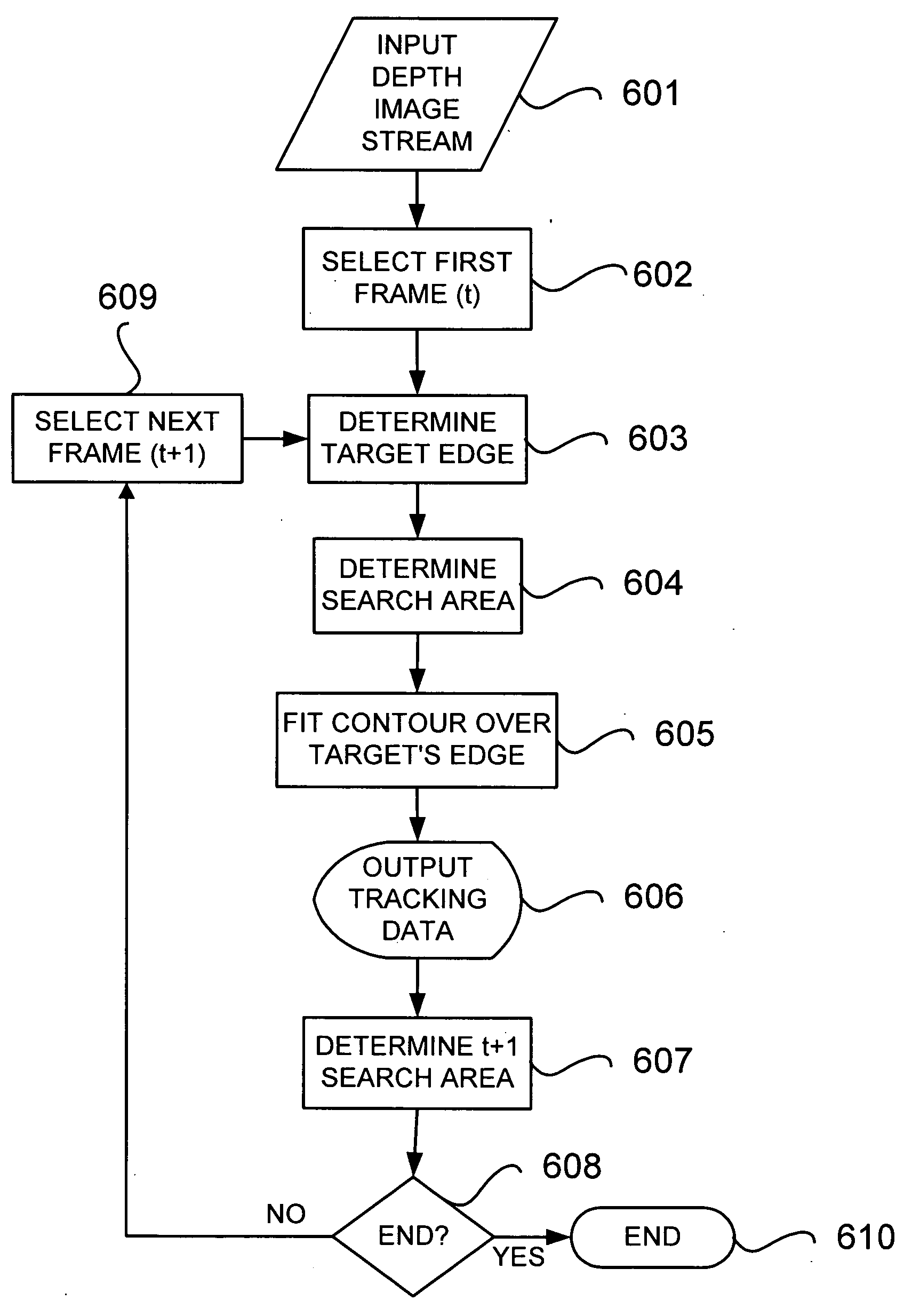
The Figures and the following description relate to preferred embodiments of the present invention by way of illustration only. It should be noted that from the following discussion, alternative embodiments of the structures and methods disclosed herein will be readily recognized as viable alternatives that may be employed without departing from the principles of the claimed invention.

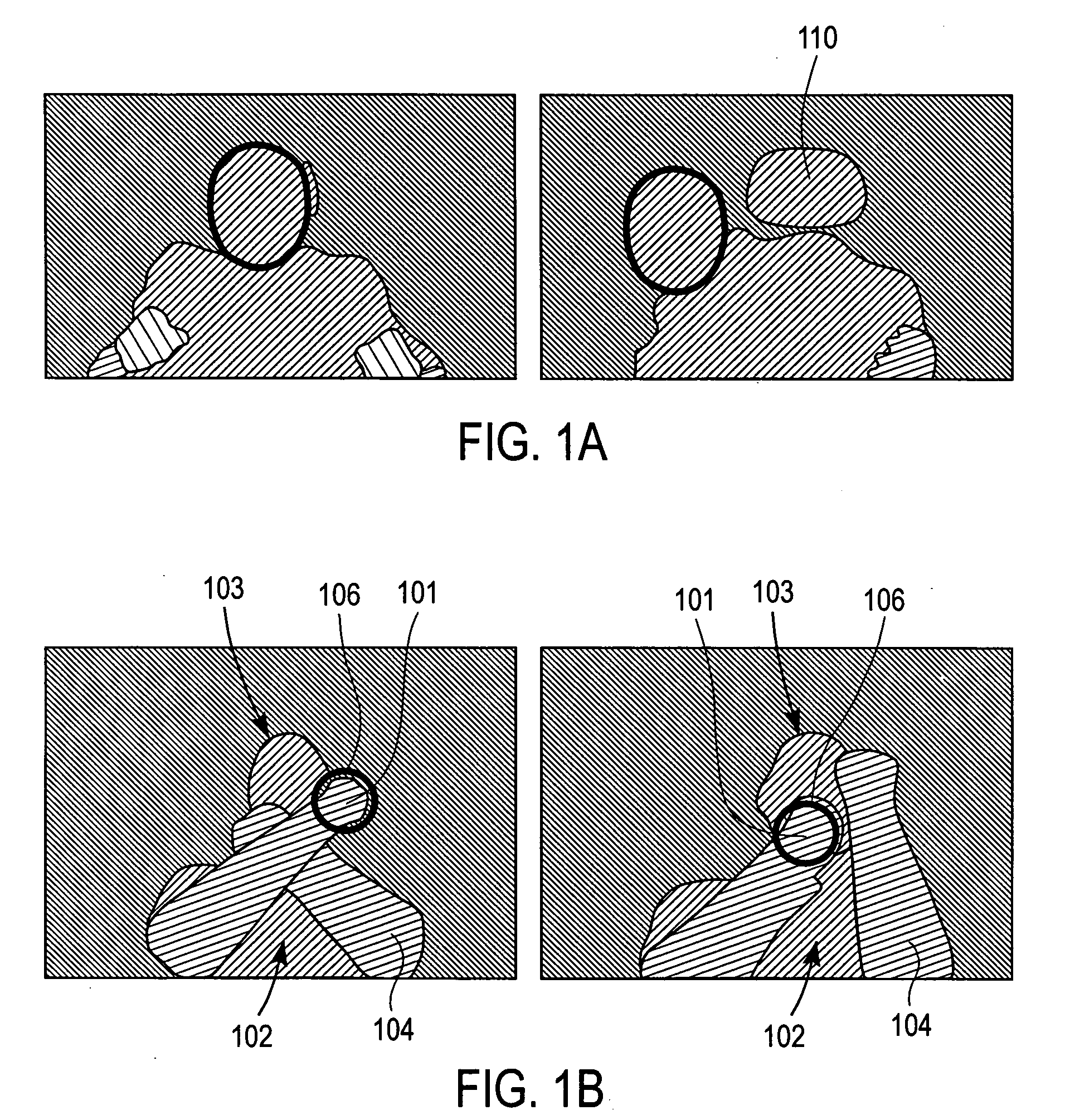
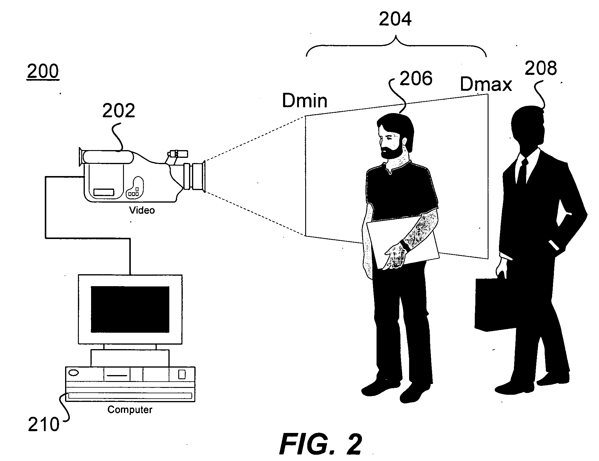
Referring now to FIG. (“FIG.”) 1A, depth images of a driver with different positions for the upper torso are shown with the output of an elliptic tracking system. A depth image is visually represented with variations in the pixel intensity based on the depth value, that is, the objects closer to the camera appear brighter and progressively darker until the background outside a depth window is shown as black. A depth sensor can be set to capture or sense depth information for objects within a specified depth range or depth window. When this is done in real-time and a stream of depth images or frames ...


PUM


Abstract

Real-time visual tracking using depth sensing camera technology, results in illumination-invariant tracking performance. Depth sensing (time-of-flight) cameras provide real-time depth and color images of the same scene. Depth windows regulate the tracked area by controlling shutter speed. A potential field is derived from the depth image data to provide edge information of the tracked target. A mathematically representable contour can model the tracked target. Based on the depth data, determining a best fit between the contour and the edge of the tracked target provides position information for tracking. Applications using depth sensor based visual tracking include head tracking, hand tracking, body-pose estimation, robotic command determination, and other human-computer interaction systems.

Description

FIELD OF THE INVENTION The present invention relates generally to real-time computer vision and more particularly to computer based visual tracking of moving targets. BACKGROUND OF THE INVENTION Tracking is a key component for many areas of real-time computer vision such as Human-Computer Interaction (“HCI”). One example of an HCI application is driver monitoring. In this area, work has been done to determine head pose and body lean using various techniques. This information can be used for example to assist an air-bag deployment system, or for attention and fatigue monitoring in a safety system. Tracking spatial location of the driver's head or other body parts facilitates the operation of these and other HCI systems. Conventional tracking systems are typically based on two-dimensional (2D) gray or color images. There are situations in which methods using templates or probabilistic frameworks do not function very robustly. Conventional tracking algorithms often fail when the env...

Claims


Application Information

Patent Timeline
IPC IPC(8): G06T1/00G06T7/20G06V10/24
CPCG06K9/00369G06T7/20G06K9/32G06K9/00375G06V40/107G06V40/103G06V10/24
Inventor FUJIMURA, KIKUONANDA, HARSH
Owner HONDA MOTOR CO LTD
Why Eureka
Try Eureka