Connector component and connector assembly

a technology of connector components and components, applied in the direction of coupling device details, coupling device connections, electric discharge lamps, etc., can solve the problem of difficulty in recognizing the light emitted from the led

Inactive Publication Date: 2005-02-10
NEC CORP
View PDF7 Cites 58 Cited by
  • Summary
  • Abstract
  • Description
  • Claims
  • Application Information

AI Technical Summary

Benefits of technology

[0007] This invention has been invented in view of the aforesaid problems and it is an object of the present invention to provide a connector component and a connector assembly in which light emitted from a light source can be easily confirmed and a connection between the modular cable and the modular jack can be visually confirmed.

Problems solved by technology

However, the aforesaid conventional technology has some problems indicated as follows.
However, when the modular jack is arranged at a deep part of a chassis of the device, it produces a problem that it is difficult to recognize the light emitted from the LED at the modular jack to confirm the connection is complete.

Method used


Image

  • Connector component and connector assembly
  • Connector component and connector assembly
  • Connector component and connector assembly

Examples


first embodiment

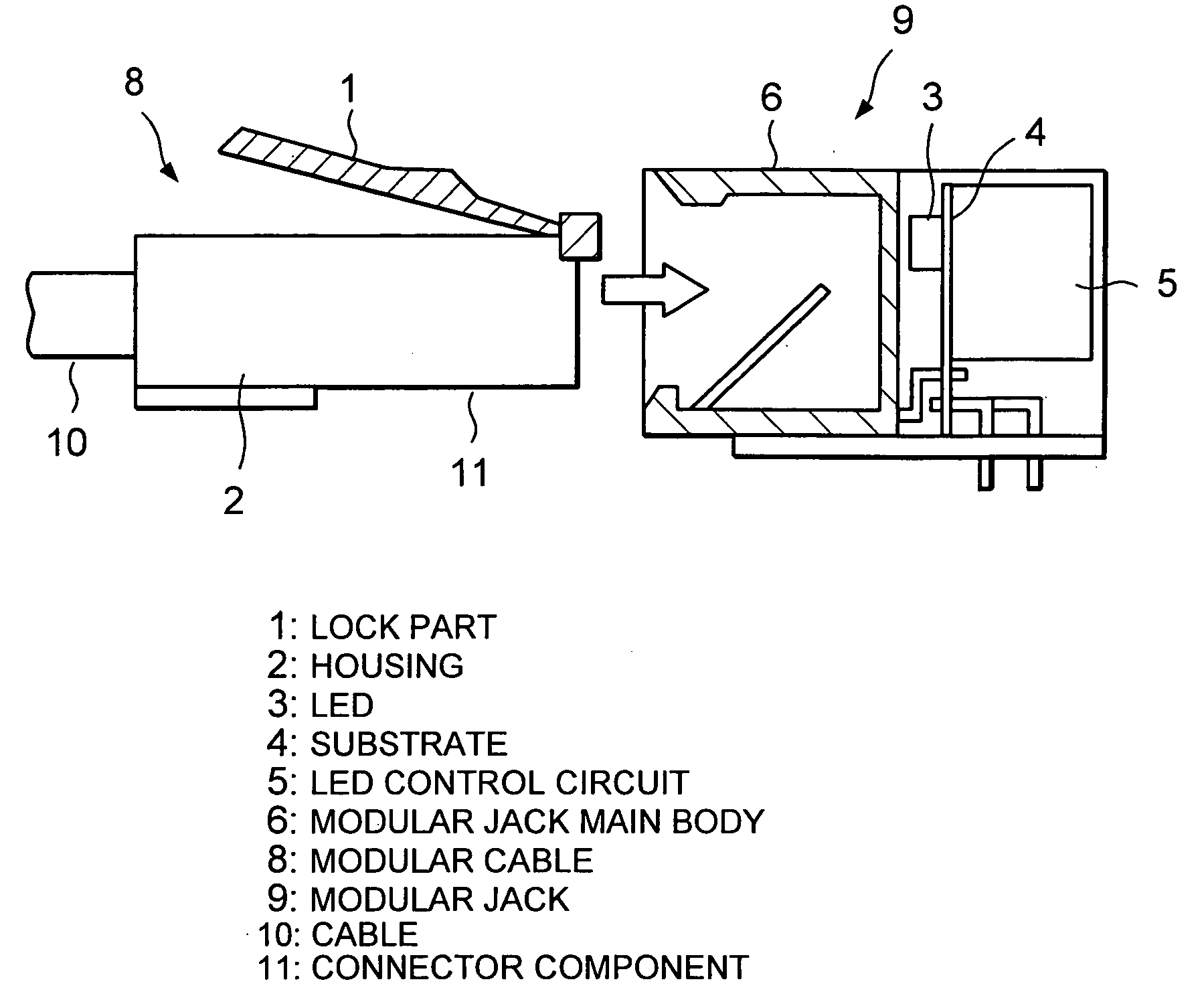
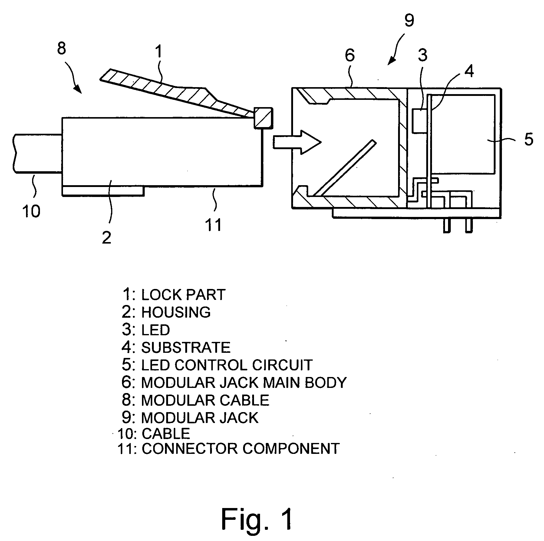
[0023] Referring to FIG. 1 showing the present invention, a connector component 11 includes a lock part 1 and a housing 2. The connector component 11 and a cable 10 compose a modular cable 8. The connector component 11 is arranged at the end of the modular cable 8 and can be inserted into a modular jack 9. The modular cable 8 is formed by the connector component 11 and the cable 10 integrally or separately.

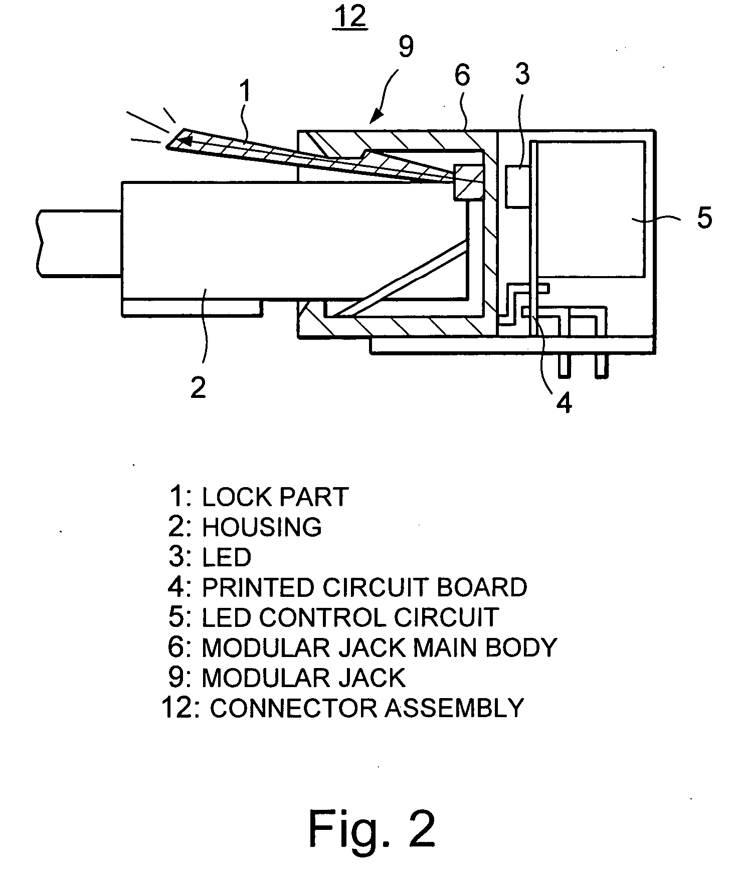
[0024] Referring now to FIG. 2, a connector assembly 12 of the preferred embodiment is formed by the modular cable 8 and a modular jack 9. The modular cable 8 and the modular jack 9 are connected while the housing 2 of the modular cable 8 is inserted in the modular jack 9.

[0025] Additionally, referring to FIGS. 1 and 2, the connector component 11 is provided with the lock part 1 acting as a lock mechanism for preventing the housing 2 from being pulled off when it is inserted into the modular jack 9. In this embodiment, the lock part 1 is formed by an optical transparent type pipe...

second embodiment

[0034] Next, the present invention will be described in detail.

[0035] A connector component and a connector assembly of the second embodiment are provided with a housing which emits light or shines when it is connected to the modular jack. In the second embodiment, the same reference numerals are given to the same structural elements as in the first embodiment of the present invention.

[0036] Referring to FIG. 3, the connecter assembly 12 has a housing 102 which emits light when the housing 102 is inserted and held in the modular jack 9. As the light source, a LED 3 is used. In this embodiment, no light emission is produced in advance by the LED 3, but the LED 3 is driven by the LED 3 control circuit 5 in such a way that light is emitted when the modular cable 8 and the modular jack 9 are electrically connected to each other.

[0037] When the LED is used for the light source, what is necessary is to make the surface of the housing 102 to reacts to or reflect the light of a light sour...

third embodiment

[0039] Next, the present invention will be described in detail.

[0040] Referring to FIG. 4, a connector component 211 is formed at the tip part of a plug 208. The connector component 211 can be connected to a receptacle 209 with screws 204. The plug 208 includes the connector component 211 and a cable 210. While any type of connector is applicable to the present invention, the plug 208 is a D-Subminiature (DSUB) plug and the receptacle 209 is a DSUB receptacle in this embodiment. A light source 203 such as LED for checking a connection state, is attached in the receptacle 209.

[0041] As shown in FIG. 5, a connector assembly 212 of the embodiment includes the receptacle 209 for connecting the connector component 211 and the plug 208. A light path is formed in a housing 202 which constitutes the connector component 211. In this embodiment, the light path is formed by an optical transparent type pipe 213. The connection state of the connector can be checked because the light enters the ...


PUM


Abstract

A connector component of the present invention includes a first connector part which includes a housing having a first end from which a cable is protruded and a second end which is connectable to a second connector part. At least a part of the first connector part emits light or shines while the first connector part is connected to the second connector part. A connector assembly of the present invention includes a first connector part which has a first end from which a cable is protruded and a second end. The connector assembly also has a second connector part which is connected to the second end of the first connector part. When the first and second connector parts are correctly connected, at least a part of first connector part emits the light.

Description

BACKGROUND OF THE INVENTION [0001] This invention relates to a connector component and a connector assembly used for transmitting a signal through a cable, and more particularly, to a connector component and a connector assembly having male and female connectors for an electronic communication equipment such as a personal computer, a server and the like. [0002] There is provided the prior art connector assembly having a light emitting diode (LED) fixed to a modular jack in order to perform a visual confirmation whether or not the modular jack and the modular cable are correctly connected to each other. For example, in the conventional connector assembly described in Japanese Utility Model Laid-Open publication No. Hei 3-112889, an optical cable is built in a modular cable and light emitted from the LED fixed to the modular jack is transmitted through this optical cable from one end to the other end of the modular cable inserted into the modular jack. Additionally, if a plurality of ...

Claims


Application Information

Patent Timeline
Patent Type & Authority Applications(United States)
IPC IPC(8): H01R13/717H01R13/641H01R13/66
CPCH01R13/641H01R13/7175H01R13/7172H01R13/6641
Inventor SAKAMOTO, RIKIO
Owner NEC CORP
Why Eureka
Try Eureka