Receiver test system

a technology for testing systems and receivers, applied in the field of measuring the performance of communication system hardware, can solve the problems of insufficient evaluation of receiver diagnostics by vendors, difficult to test the performance of receivers in the field, and the only way to achieve true receiver sensitivity testing of analog receivers

Inactive Publication Date: 2005-02-10
AT&T WIRELESS SERVICES
View PDF13 Cites 19 Cited by
  • Summary
  • Abstract
  • Description
  • Claims
  • Application Information

AI Technical Summary

Benefits of technology

[0024] One embodiment of the invention discloses a receiver test unit having a controller, a programmable attenuator, a mobile station, and a power measurement device. The controller is capable of initiating a communication link to a remote device such as an MSC test unit, wirelessly transmitting a predetermined message over the communication link via the mobile station, reading the received signal power of the predetermined message at a point prior to the incoming-signal input of the receiver-under-test via the power measurement device, and adjusting the attenuation of subsequent transmissions of predetermined messages in accordance with the received signal power measurement. The performance of the receiver-under-test can then be determined by its ability to reconstruct the predetermined message at various transmission attenuations from the receiver test unit.

Problems solved by technology

In general, cellular service providers, like most communication service providers, do not manufacture the computers and other infrastructure necessary to create and maintain a cellular network.
Receiver diagnostics, however, have not been adequately addressed by the vendors.
It has always been difficult to test performance of receivers in the field.
Historically, true receiver sensitivity testing of analog receivers could only be accomplished by taking manual control of the radios on-site.
Unfortunately, digital receivers are not capable of being performance tested in the same manner as analog receivers.
As a result, network operators have generally fallen back on statistical methods of monitoring of digital receiver performance.
Modern communication networks have no way to determine the actual performance of field-deployed receivers.
In most cellular communication networks, it is especially difficult to field test receivers because the air interface is constantly powering the mobile up and down.
Thus, poorly performing receivers that cause degraded network performance must be located by an expensive and time consuming process of trial and error.
Often, however, lack of adequate methods to field test receivers means that the source of network problems cannot be identified.

Method used


Image

  • Receiver test system
  • Receiver test system
  • Receiver test system

Examples


Embodiment Construction

[0032] The invention will now be described with respect to various embodiments. The following description provides specific details for a thorough understanding of, and enabling description for, these embodiments of the invention. However, one skilled in the art will understand that the invention may be practiced without these details.

[0033] In other instances, well known structures and functions have not been shown or described in detail to avoid unnecessarily obscuring the description of the embodiments of the invention.

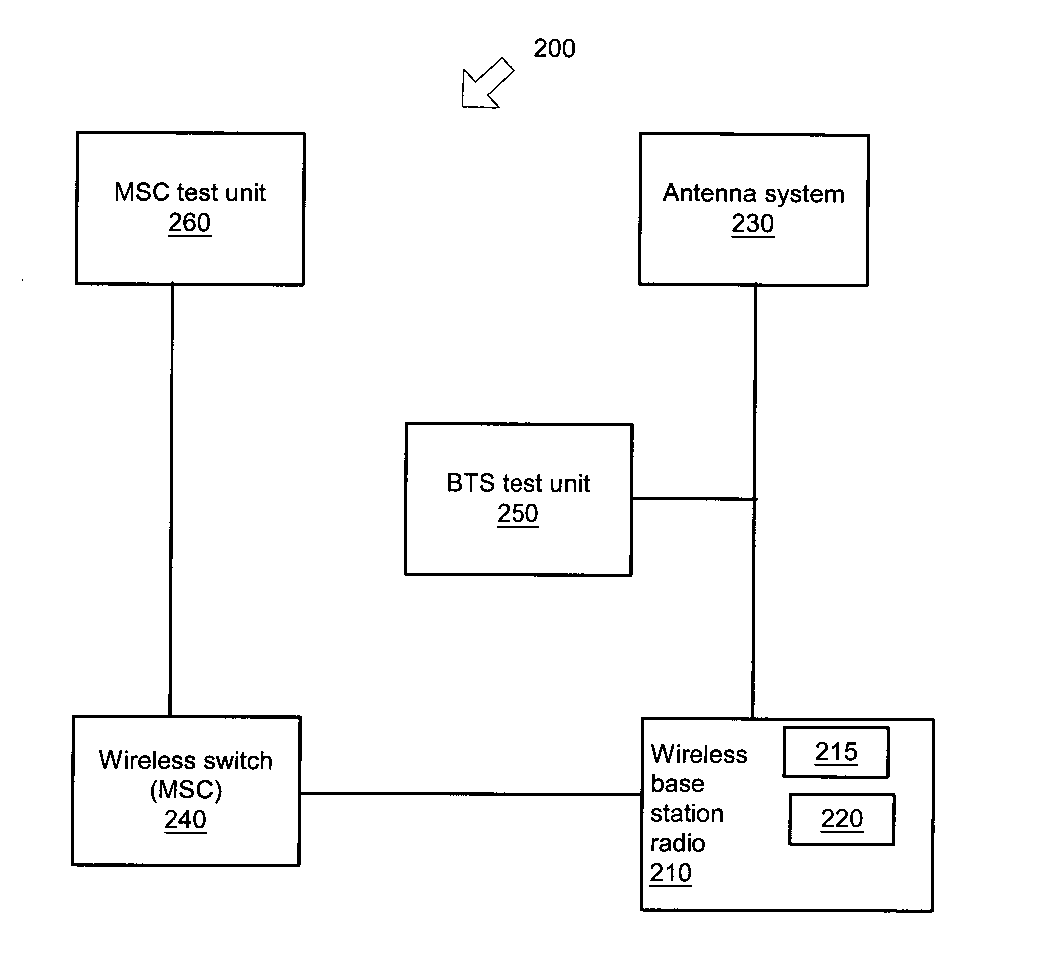
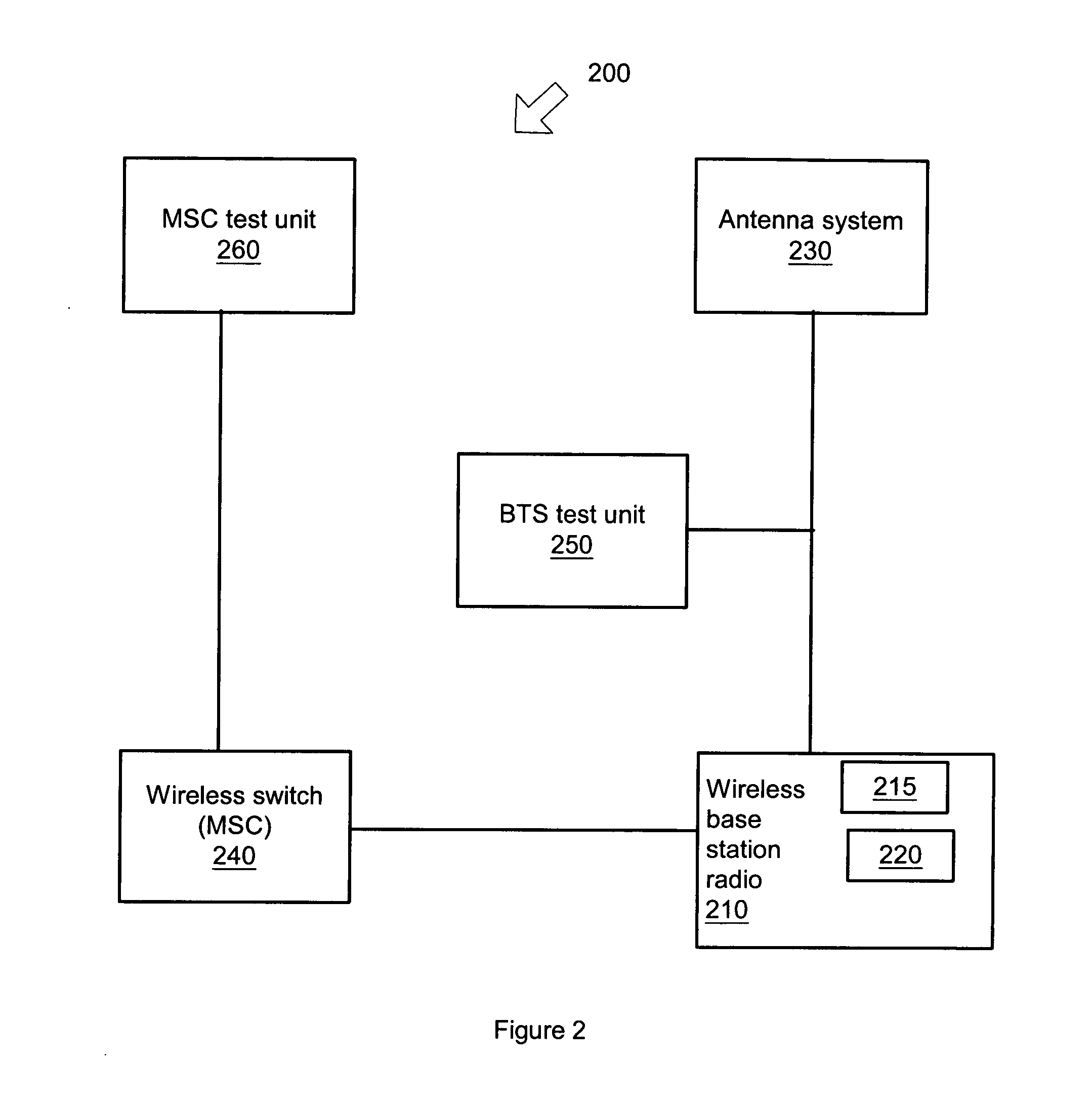
[0034] An embodiment of the invention is shown in a radio base station receiver testing system 200 of FIG. 2. A cellular radio base transceiver station 210 having a transmitter 215 and receiver 220 is coupled to an antenna system 230, a wireless switch (MSC) 240 and a base station transceiver test unit (BTU) 250. MSC 240 is coupled to MSC Test Unit (MTU) 260. In the embodiment shown in FIG. 2, receiver 220 is the receiver-under-test.

[0035] Some elements typical ...


PUM


Abstract

Performance of receivers can be determined by automated or manual testing of receivers without interrupting communication service to users of the communication system. In one embodiment, the system measures the performance of a deployed base station receiver without interrupting cellular service to subscribers registered with the base station.

Description

TECHNICAL FIELD [0001] The present disclosure relates to measuring performance of communication system hardware and, in particular, relates to testing of receivers. BACKGROUND [0002] Many types of wireless communication networks exist to serve society's increasing desire to be “connected” at all times. Some examples are mobile telephone systems such as cellular networks, wireless local-area-networks (WLAN) such as IEEE 802.11 compliant networks, wireless wide-area networks (WWAN), short range RF systems such as Bluetooth, and fixed wireless broadband networks. Mobile telephone systems commonly include a variety of services and functions beyond simple direct voice communication. There are many more types of wireless communication networks in use. [0003]FIG. 1 shows a functional block diagram of a typical cellular network 100. A radio subsystem 105 includes all the radio-related functions of the network: a mobile station (MS) 110 and the base station subsystem 115. The base station su...

Claims


Application Information

Patent Timeline
Patent Type & Authority Applications(United States)
IPC IPC(8): H04B17/00H04W24/00
CPCH04B17/309H04W24/00
Inventor SWANT, JOHN M.
Owner AT&T WIRELESS SERVICES
Why Eureka
Try Eureka