Apparatus for inspecting a lateral conduit

Inactive Publication Date: 2005-02-17
HATHORN CORP
View PDF13 Cites 7 Cited by
  • Summary
  • Abstract
  • Description
  • Claims
  • Application Information

AI Technical Summary

Benefits of technology

[0013] In one embodiment, the upper and lower tracks are metal chains. In that embodiment, the upper and lower pre

Problems solved by technology

A problem that occurs with the use of these types of apparatuses is that the push rod drive assembly pierces or otherwise damages the surface of the push rod.
Usually this occurs because the push rod drive assembly applies excess

Method used


Image

  • Apparatus for inspecting a lateral conduit
  • Apparatus for inspecting a lateral conduit
  • Apparatus for inspecting a lateral conduit

Examples


Example

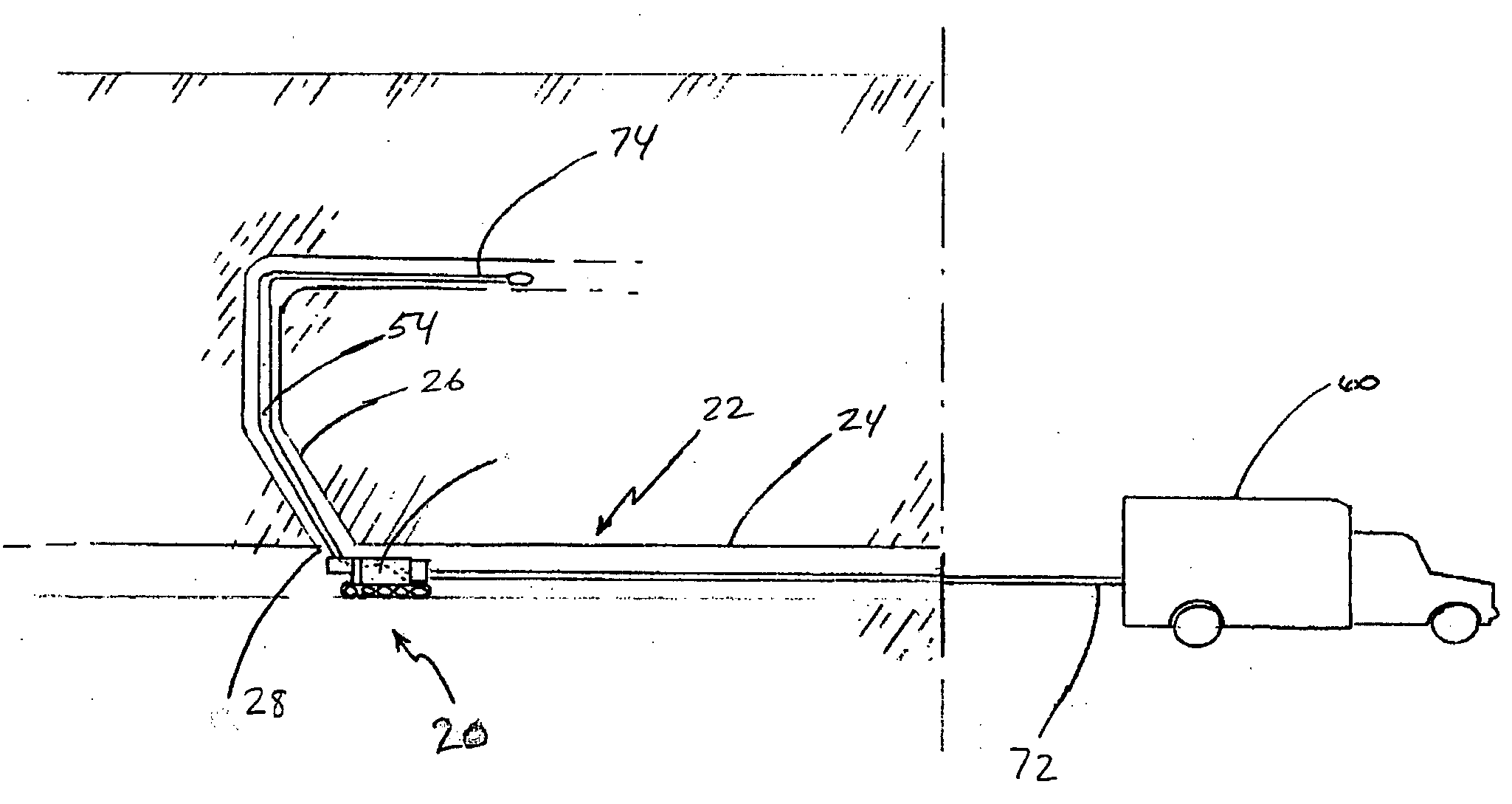
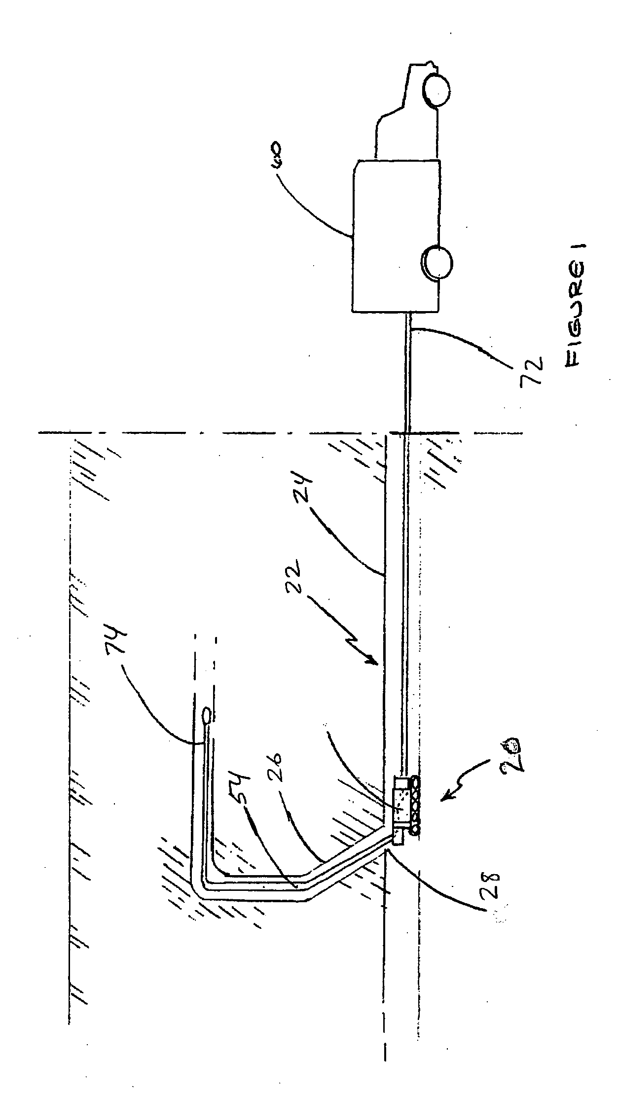
[0024] Reference is first made to FIG. 1, which illustrates an inspection apparatus 20 made in accordance with a first exemplary embodiment of the invention. Apparatus 20 is positioned inside a conduit system 22 comprising a main conduit 24, a lateral conduit 26 and a junction 28. Apparatus 20 is adapted for inspecting at least a portion of lateral conduit 26 extending from main conduit 24 to determine whether any maintenance of conduit system 22 is required. Various types of maintenance concerns may be revealed during inspection of conduit system 22, such as, for example, obstructions, insufficient flow capacity or discontinuities in the interior surface of lateral conduit 26.

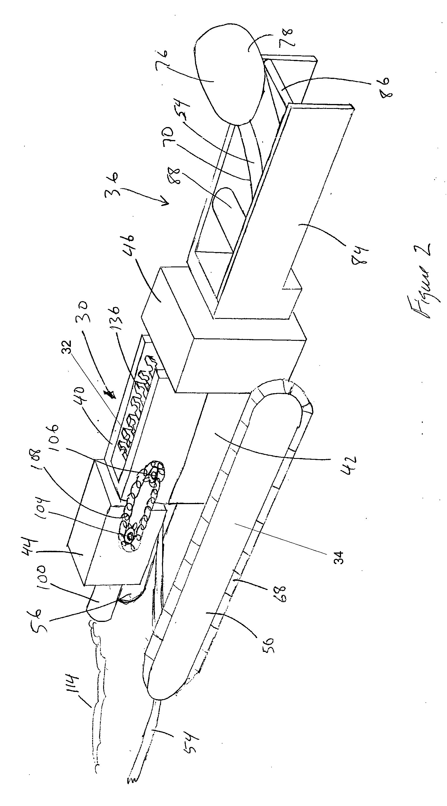
[0025] Reference is made to FIG. 2. Apparatus 20 comprises a frame 30, a push rod drive assembly 32, a propulsion mechanism 34 and a deflector assembly 36.

[0026] Frame 30 includes an upper frame section 40, a lower frame section 42, and frame sections 44, 46. Frame 30 will typically include cover members (no...


PUM


Abstract

An apparatus for inspecting a lateral conduit from a main conduit including a frame, an upper push rod drive assembly and a lower push rod drive assembly. The upper push rod drive assembly includes an upper track having a plurality of upper attachments mounted thereto for engaging the push rod. The lower push rod drive assembly includes a lower track having a plurality of lower attachments mounted thereto for engaging the push rod. The push rod is held between the upper and lower attachments and in a preferred embodiment, some of the upper attachments, some of the lower attachments and the push rod move with a linearly synchronized motion.

Description

FIELD OF THE INVENTION [0001] This invention relates to an apparatus for inspecting lateral sewer and drain pipes or conduits. More particularly, the invention relates to a mechanism for controlling the extension and retraction of a push rod of such apparatuses. BACKGROUND OF THE INVENTION [0002] A wide variety of apparatuses have been developed for inspecting the interior of a lateral conduit for maintenance concerns, such as cracks and leaks. Typically, these apparatuses include a push rod, a push rod drive assembly and a camera mounted to the push rod. The apparatus can be remotely guided into a main conduit. The apparatus is advanced into the main conduit and positioned near a junction with a lateral conduit. The push rod and camera are then extended into the lateral conduit using the drive assembly to allow an inspector to view the interior of the conduit on a remote monitor coupled to the camera. When the lateral conduit has been inspected, the push rod and camera are retracte...

Claims


Application Information

Patent Timeline
IPC IPC(8): G01M99/00F16L55/26F16L55/30G01N21/954
CPCF16L55/265G01N21/954F16L2101/30F16L55/30
Inventor THORNHILL, BRUCEHA, BINH
Owner HATHORN CORP
Why Eureka
Try Eureka