Polarized light emitting devices and methods

a light-emitting device and organic technology, applied in the field of polarized organic light-emitting devices, can solve the problems of reducing the life span of the oled, obviating the problem of washout, and the same drawbacks

Inactive Publication Date: 2005-02-17
PETERSON CHARLES M +1
View PDF15 Cites 26 Cited by
  • Summary
  • Abstract
  • Description
  • Claims
  • Application Information

AI Technical Summary

Problems solved by technology

This is a particular problem with organic light emitting devices (OLEDs) because OLEDs are generally fabricated with a highly reflective cathode and surface interfaces that have a large change in refractive index.
Unfortunately, currently available OLEDs emit both polarization states of light and the circular polarizer absorbs one of the two polarization states of the light produced by the OLED.
This additional light is produced by the application of additional power to the OLED which reduces the life span of the OLED.
The absorbing material absorbs the majority of ambient light incident on the display such that the wash out problem is obviated.
However, since the OLED device is backed by an absorbing material instead of being backed by a reflector, only about half of the light emitted from the emissive layer of the OLED is used to form the image.
Thus, to keep the display luminance at the same level as a device with a reflective cathode, the OLED must be made to emit additional light which results in the same drawbacks that occur with the inclusion of a circular polarizer.
Similar viewing washout problems result in projection systems wherein images are viewed on a larger screen in a variety of ambient lighting conditions.
Unfortunately, the amount of light energy delivered to the viewing screen per unit area is considerable less that direct view display systems.
The increased excitation current substantially shortens the lifetimes of the OLED and creates other problems.
Unfortunately, the aperture of a system using such a screen is significantly less than 100% and results in a substantial loss of light emitted by the OLED.

Method used


Image

  • Polarized light emitting devices and methods
  • Polarized light emitting devices and methods
  • Polarized light emitting devices and methods

Examples


Embodiment Construction

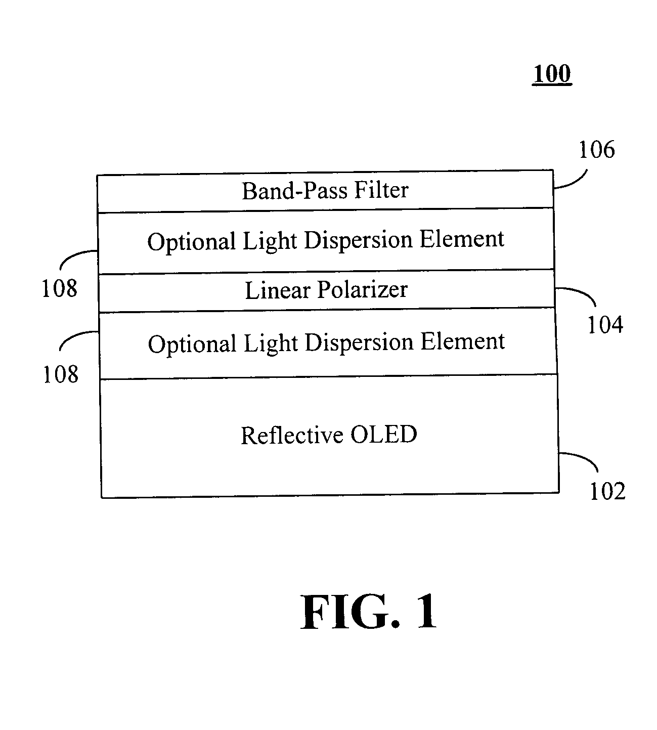
A polarized organic light emitting device (OLED) including a linear polarizer and / or a band-pass filter may be fabricated that substantially reduces or eliminates unwanted ambient light reflections. FIG. 1 illustrates one exemplary embodiment of such a device 100 that includes a plane polarized light emitting OLED 102 with a reflective electrode or reflective backing, with linear polarizing film 104, and with a band-pass filter 106 laminated or otherwise attached to its front surface. Alternatively, the polarizing film104 and band-pass filter 106 may be separated from the device 100 by some distance and housed in a structure that maintains the relationship of the polarized emission of the OLED 102 and the polarization axis of the polarizing film 104. Optional anti-reflective or antiglare coatings may be used to reduce surface reflections of the separated elements. The linear polarizing film 104 transmits one linearly polarized state of light and absorbs the other. The polarizing fil...


PUM

PropertyMeasurementUnit
spectrumaaaaaaaaaa
reflectivityaaaaaaaaaa
emission spectrumaaaaaaaaaa

Abstract

An organic light emitting device (OLED) including a reflective electrode or reflective backing that emits polarized light, a linear polarizer and/or a band-pass filter may be combined such that substantially all of the light from the OLED is transmitted through the linear polarizer and/or the band-pass filer while ambient light is substantially absorbed. A colored linear polarizer may be to provide the functions of the linear polarizer and the band-pass filer. A light dispersion element also may be included.

Description

FIELD OF THE INVENTION The present invention relates generally to a polarized organic light emitting device (OLED) including a polarizer and / or filter, and more particularly, to an OLED with polarized emission including polarizer and / or filter that substantially attenuates ambient light to enhance viewability, and still more particularly, to an OLED with polarized emission including polarizer and / or filter that substantially attenuates ambient light to enhance viewability in combination with a light dispersive element used to alter the viewing field of the image. BACKGROUND Emissive electronic light emitting devices are used in a hundreds of different kinds of devices that are used in a variety of environments. In some of these environments, the images produced by the devices may appear “washed out” when viewed under a high level of ambient illumination such as in direct sunlight. This may occur when illuminating light is reflected by the front surface of the display or is reflect...

Claims


Application Information

Patent Timeline
Patent Type & Authority Applications(United States)
IPC IPC(8): G02F1/13357H01L51/52
CPCG02F1/133603H01L51/5281H01L51/5265G02F1/13362H10K50/852H10K50/86H05B33/22H05B33/02
Inventor PETERSON, CHARLES M.KOCH, GENE C.
Owner PETERSON CHARLES M
Why Eureka
Try Eureka