Valved catheter

a valved catheter and valve tube technology, applied in the field of multi-lumen catheters, can solve the problems of significant reduction of flow rate, damage or deformation of extension lines, blood vessel trauma, etc., and achieve the effect of preventing blood evacuation and anti-coagulant leakage, convenient and efficient manufacturing and assembly, and facilitating fluid flow in the bi-directional direction

Active Publication Date: 2005-02-17
COVIDIEN AG
View PDF21 Cites 60 Cited by
  • Summary
  • Abstract
  • Description
  • Claims
  • Application Information

AI Technical Summary

Benefits of technology

[0008] Accordingly, a catheter apparatus is provided that facilitates bi-directional fluid flow by employing a multiple lumen body having a valve configuration that prevents thrombosis and may break up fibrin sheath to overcome the disadvantages and drawbacks of the prior art. Desirably, such a catheter apparatus includes a multiple valve configuration that prevents blood evacuation and anti-coagulant leakage. Most desirably the catheter apparatus has a smaller relative design to achieve the principles of the present disclosure. The catheter apparatus is easily and efficiently manufactured and assembled. The present disclosure resolves related disadvantages and drawbacks experienced in the art.

Problems solved by technology

These devices, however, require two separate punctures with the associated discomfort, possibility for infection, and consequent trauma to the blood vessels.
The above mentioned catheter devices, however, typically require clamping of the tubular portions or lumens when fluid administration is not being performed.
This type of structure can result in several drawbacks.
This results in a flow restriction that can significantly reduce flow rate.
Further, the clamps of these catheter devices may fail and / or may cause damage or deformation to the extension lines, particularly in those devices employed for extended periods of use, such as chronic catheters.
Failure may result in undesirable blood evacuation, heparin leakage, etc.
Moreover, devices employing clamps are generally bulky and cumbersome.

Method used


Image

  • Valved catheter
  • Valved catheter
  • Valved catheter

Examples


Embodiment Construction

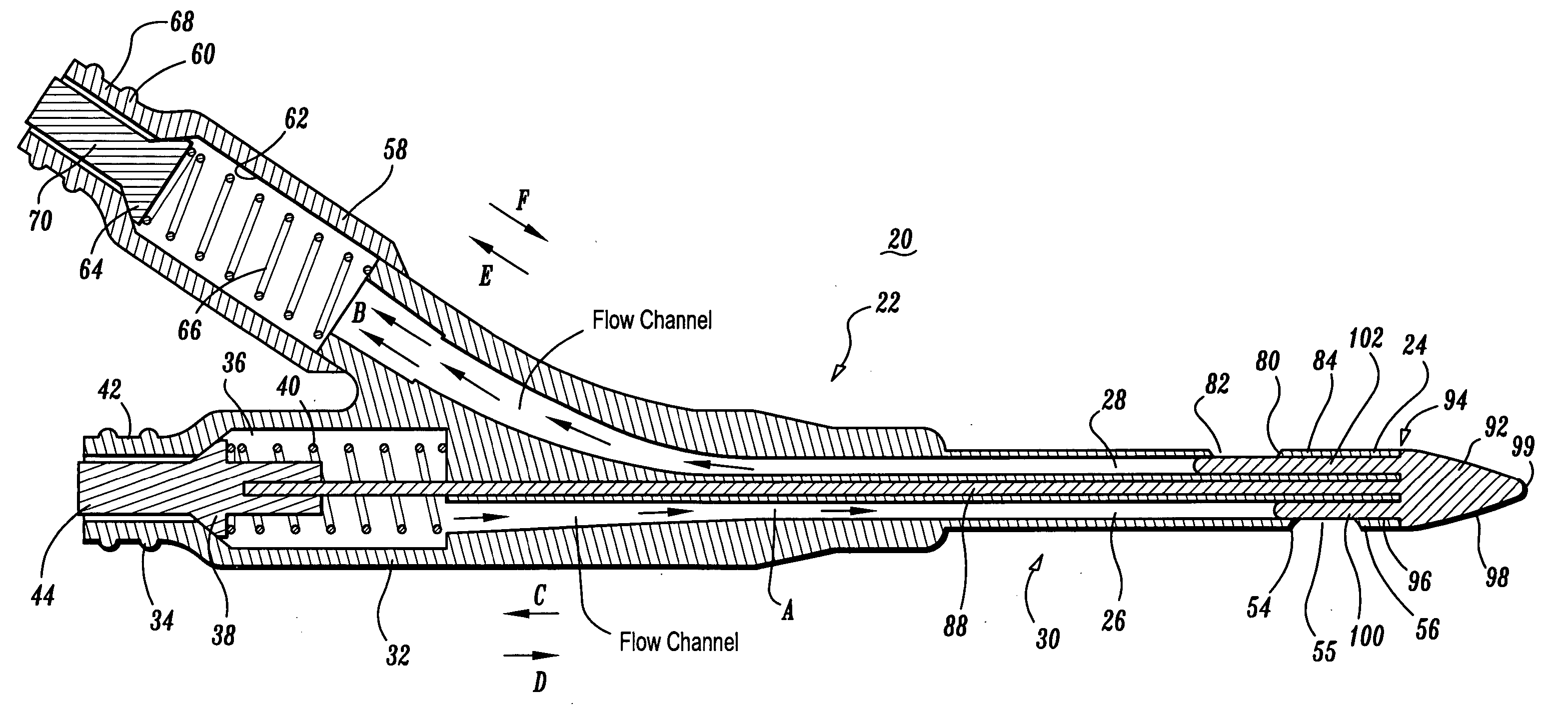
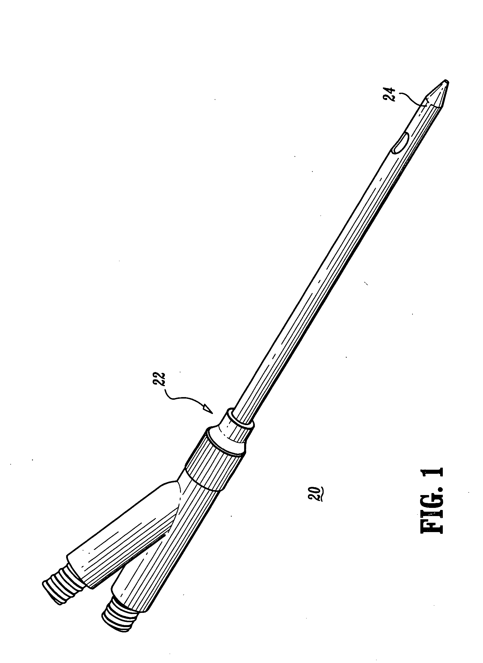
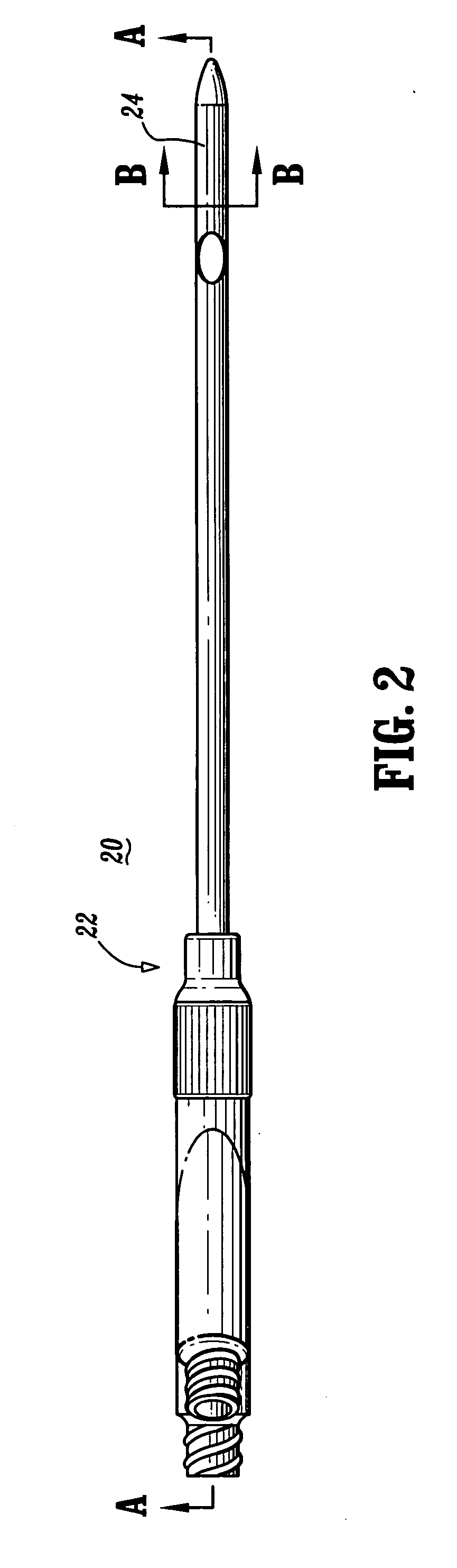
[0040] The exemplary embodiments of the catheter apparatus and methods of use disclosed are discussed in terms of medical catheters for the administration of fluids (withdrawal, introduction, etc.) with the body of a subject and more particularly, in terms of a catheter apparatus that facilitates bidirectional fluid flow by employing a multiple lumen body having a valve configuration that prevents thrombosis and fibrin sheath formation. It is envisioned that the present disclosure may be employed with a range of catheter applications including surgical, diagnostic and related treatments of diseases, body ailments, etc. of a subject. It is further envisioned that the principles relating to the catheter apparatus disclosed include employment with various catheter related procedures, such as, for example, hemodialysis, cardiac, abdominal, urinary, intestinal, etc., in chronic, acute, etc. applications. It is contemplated that the catheter apparatus can be used for administration of flu...


PUM


Abstract

A catheter apparatus is provided that includes a tubular body having a distal end. The body defines first and second lumens. The first lumen has a first adapter that includes a first valve biased to seal the proximal end. The first lumen defines a first lateral port and the second lumen defines a second lateral port. A push rod is connected to the first valve for corresponding movement therewith and extends to a tip. The tip includes a first member extending into the first lumen and a second member extending into the second lumen such that the first member seals the first lateral port and the second member seals the second lateral port in a closed position of the tip. The first valve is engageable such that fluid communication is established between the proximal end of the first lumen and the first lumen, and the first and second members move to an open position whereby fluid communication is established. The first and second lumens may be coaxial whereby the first lumen has a first port that seals a second port of the second lumen.

Description

BACKGROUND [0001] 1. Technical Field [0002] The present disclosure generally relates to medical catheter apparatus and, more particularly, to a multiple lumen catheter apparatus that facilitates bi-directional fluid flow. [0003] 2. Description of the Related Art [0004] Some known catheters are tubular, flexible medical devices for administration of fluids (withdrawal, introduction, etc.) with cavities, ducts, vessels, etc. of a body. Typically, catheter devices are inserted with the cavity of a body via a sheath, stylet, trocar, etc. [0005] These catheter devices may be employed for administration of fluids that includes the simultaneous introduction and withdrawal of fluid for applications such as, surgery, treatment, diagnosis, etc. For example, in one particular hemodialysis application, blood is withdrawn from a blood vessel for treatment by an artificial kidney device and the treated blood is introduced back into the blood vessel. Various known catheter devices have been employ...

Claims


Application Information

Patent Timeline
Patent Type & Authority Applications(United States)
IPC IPC(8): A61M39/02A61M39/26
CPCA61M25/003A61M25/0032A61M25/007A61M2025/0039A61M39/02A61M39/26A61M2025/0031A61M25/0075
Inventor SANSOUCY, MICHAEL
Owner COVIDIEN AG
Why Eureka
Try Eureka