Quick-release drill-guide assembly for bone-plate

a drill-guide and plate technology, applied in bone drill guides, medical science, surgery, etc., can solve the problems of small margin for error in spinal surgery, limiting the dimensions of vertebral bone available for setting fasteners, and a risk of tissue damage and spinal cord injury

Active Publication Date: 2005-02-17
SYNTHES USA
View PDF99 Cites 91 Cited by
  • Summary
  • Abstract
  • Description
  • Claims
  • Application Information

AI Technical Summary

Problems solved by technology

The margin for error in spinal surgery is quite small, particularly because of the sensitivity of the spinal cord and the risk inherent with invasive procedures around the spinal cord.
In particular, the dimensions of vertebral bone available for setting fasteners are fairly ...

Method used


Image

  • Quick-release drill-guide assembly for bone-plate
  • Quick-release drill-guide assembly for bone-plate
  • Quick-release drill-guide assembly for bone-plate

Examples


Embodiment Construction

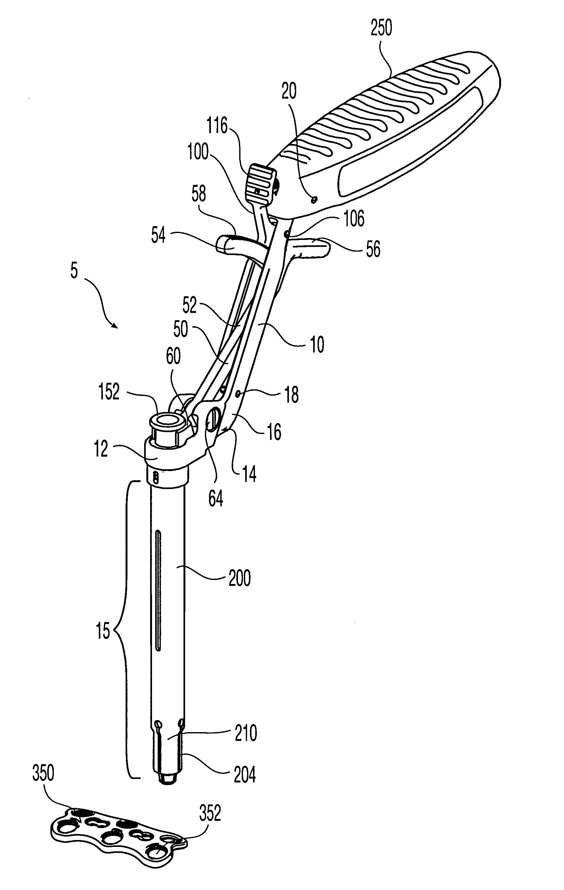
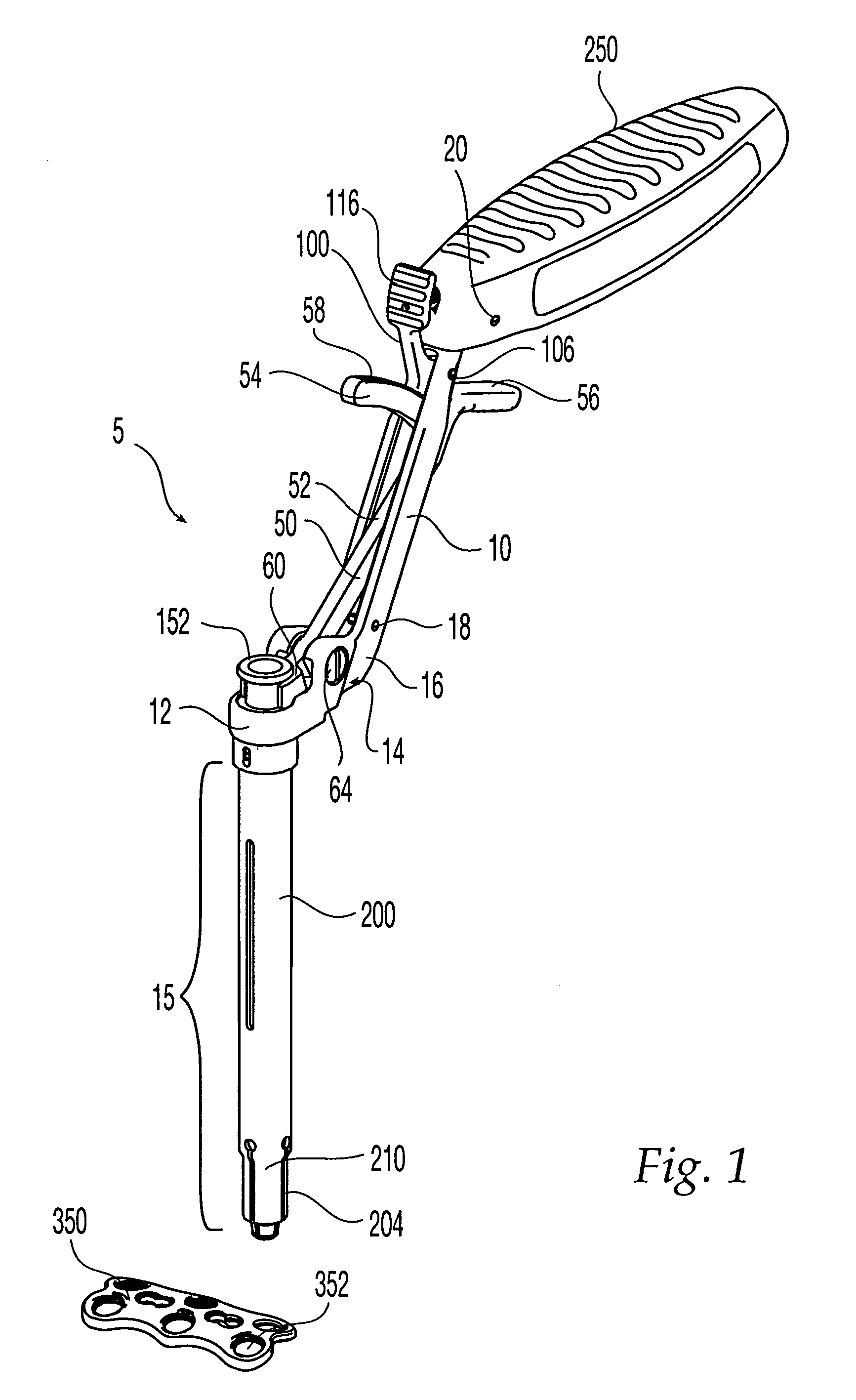
[0030] Referring to FIG. 1, there is shown an exemplary surgical drill-guide assembly 5, which is adapted for use with a cervical spine-locking bone plate having a plurality of fastener holes. While the surgical drill-guide assembly is described in conjunction with a cervical locking plate it will be appreciated that the reference to a cervical locking plate is only exemplary, and that the surgical drill-guide assembly can be used with a variety of bone plates, including a locking and a nonlocking bone-plate as well as for example, bone plates for long bones, maxillofacial applications, etc.

[0031] The drill-guide assembly 5 can be secured or locked into a fastener hole in a bone plate. Locking or securing may facilitate precision in the surgical procedure, for example, drilling or fastening screws or other similar fasteners. Moreover, the drill-guide can be quickly detached and released from the bone-plate improving the speed of surgical procedures involving drilling or similar pro...


PUM


Abstract

The present invention relates to a surgical drill-guide assembly that can be releasably attached to a part of a bone-fixation system, for example, a plate. The surgical drill-guide assembly of the present invention is used for example, to guide a drill, screw, bone fastener, or other instrument or fastener into bone.

Description

FIELD OF THE INVENTION [0001] The present invention relates to a surgical drill-guide assembly that can be releasably attached to a part of a bone-fixation system, for example, a bone plate. The surgical drill-guide assembly of the present invention is used for example, to guide a drill-bit, screw, bone fastener, or other instrument or fastener into bone or other tissue. BACKGROUND [0002] The use of surgical fixation plates for a variety of orthopedic applications is widely accepted. The plates are used by surgeons or users to stabilize, mend, or align a patient's bone as well as alter compression of patient's bones. Plates are typically fastened to the bones with a plurality of fasteners such as screws that are installed through holes in the plate. Proper orientation and alignment of fasteners and secure surgical fixation of the plates can mitigate some of the potential future complications after implantation. [0003] Bone plates used, for example, in spinal applications must be ins...

Claims


Application Information

Patent Timeline
IPC IPC(8): A61B17/00A61B17/17
CPCA61B17/1728A61B17/1757A61B2017/0042A61B17/16A61B17/17
Inventor BINDER, LAWRENCE J. JR.RYAN, CHRISTOPHER J.
Owner SYNTHES USA
Why Eureka
Try Eureka