Suction cleaner

a technology for vacuum cleaners and cleaning equipment, which is applied in the direction of vacuum cleaners, cleaning equipment, domestic applications, etc., can solve the problems of difficult to apply a powerful suction pressure in such a place, the agitator cannot be driven, etc., and achieves gentle suction pressure, increased rigidity of coordinating means, and enhanced usability

Inactive Publication Date: 2005-02-24
SHARP KK
View PDF14 Cites 15 Cited by
  • Summary
  • Abstract
  • Description
  • Claims
  • Application Information

AI Technical Summary

Benefits of technology

[0004] According to the present invention, in a suction cleaner that sucks in, along with an air stream produced as an electric blower is operated, dust through a suction mouth formed in a suction mouth unit and then introduces the air stream thus sucked in into a dust collecting device to collect the dust, a plurality of suction mouths including a first suction mouth are formed in the suction mouth unit, another suction mouth is formed in at least part of a region in front of the first suction mouth, an agitator is arranged in the first suction mouth, a suction mouth switching device is provided that permits selective use of the plurality of suction mouths, and the agitator is driven when suction is performed through the first suction mouth. With this construction, it is possible to selectively use different suction mouths according to whether or not to use the agitator, as on a floor surface where the use of the agitator is desirable, in particular on a carpet, and on a floor surface where the use of the agitator is undesirable. Moreover, when the first suction mouth is selected, the agitator can be driven and, otherwise, the agitator cannot be driven. This prevents the agitator from being driven when a suction mouth that is not fitted with an agitator is selected. Furthermore, whereas the first suction mouth fitted with the agitator cannot be brought close to a corner where a floor meets a wall or a piece of furniture, making it difficult to apply a powerful suction pressure in such a place, the other suction mouth formed in front of the first suction mouth can be brought close to such a corner, making it possible to apply a powerful suction pressure there.
[0005] In the suction cleaner constructed as described above, the agitator is driven with motive power different from that with which the electric blower is driven. With this construction, it is possible to simplify the mechanism for coordinating the switching to the first suction mouth with the driving of the agitator, and also to achieve that coordination easily.
[0006] In the suction cleaner constructed as described above, a motive power transmission mechanism for transmitting motive power to the agitator includes a drive pulley that rotates together with the agitator, an idler that can rotate independently of the agitator, and a belt that is shifted by a belt shifting device between a state in which it is wound on the drive pulley and a state in which it is wound on the idler. With this construction, it is possible to wind the belt on the idler to stop the agitator. Moreover, it is possible to derive motive power from the electric blower by way of the belt. This helps produce the mechanism for driving the agitator at low cost.

Problems solved by technology

With this construction, it is possible to selectively use different suction mouths according to whether or not to use the agitator, as on a floor surface where the use of the agitator is desirable, in particular on a carpet, and on a floor surface where the use of the agitator is undesirable.
Moreover, when the first suction mouth is selected, the agitator can be driven and, otherwise, the agitator cannot be driven.
Furthermore, whereas the first suction mouth fitted with the agitator cannot be brought close to a corner where a floor meets a wall or a piece of furniture, making it difficult to apply a powerful suction pressure in such a place, the other suction mouth formed in front of the first suction mouth can be brought close to such a corner, making it possible to apply a powerful suction pressure there.

Method used


Image

  • Suction cleaner
  • Suction cleaner
  • Suction cleaner

Examples


first embodiment

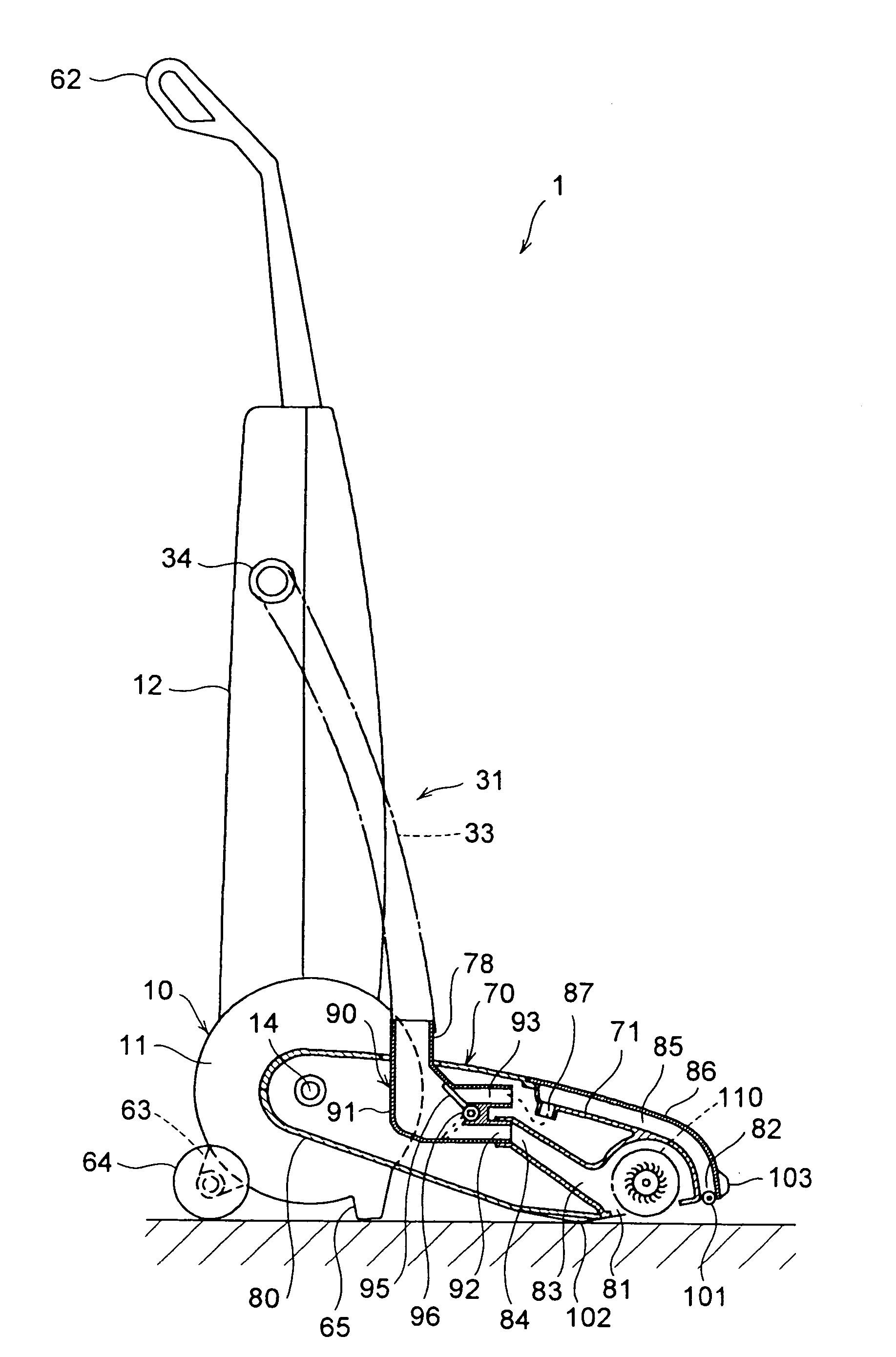
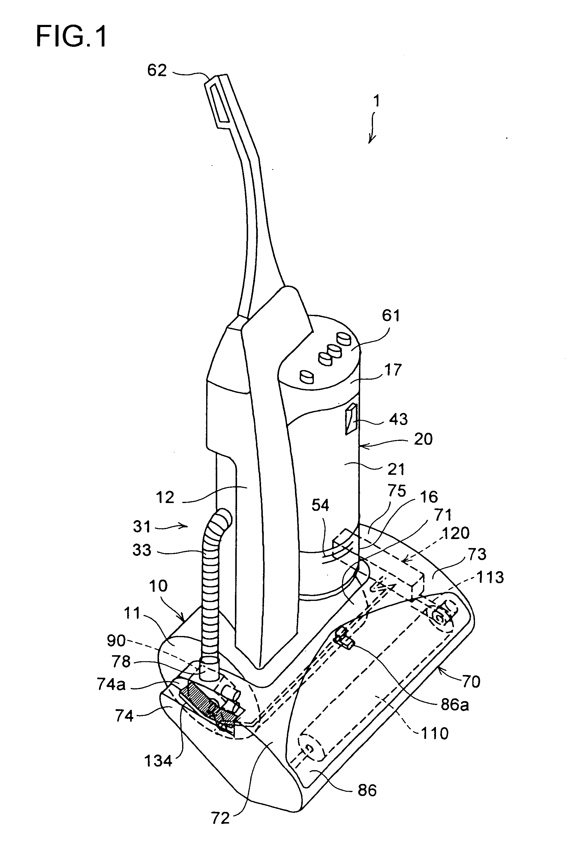
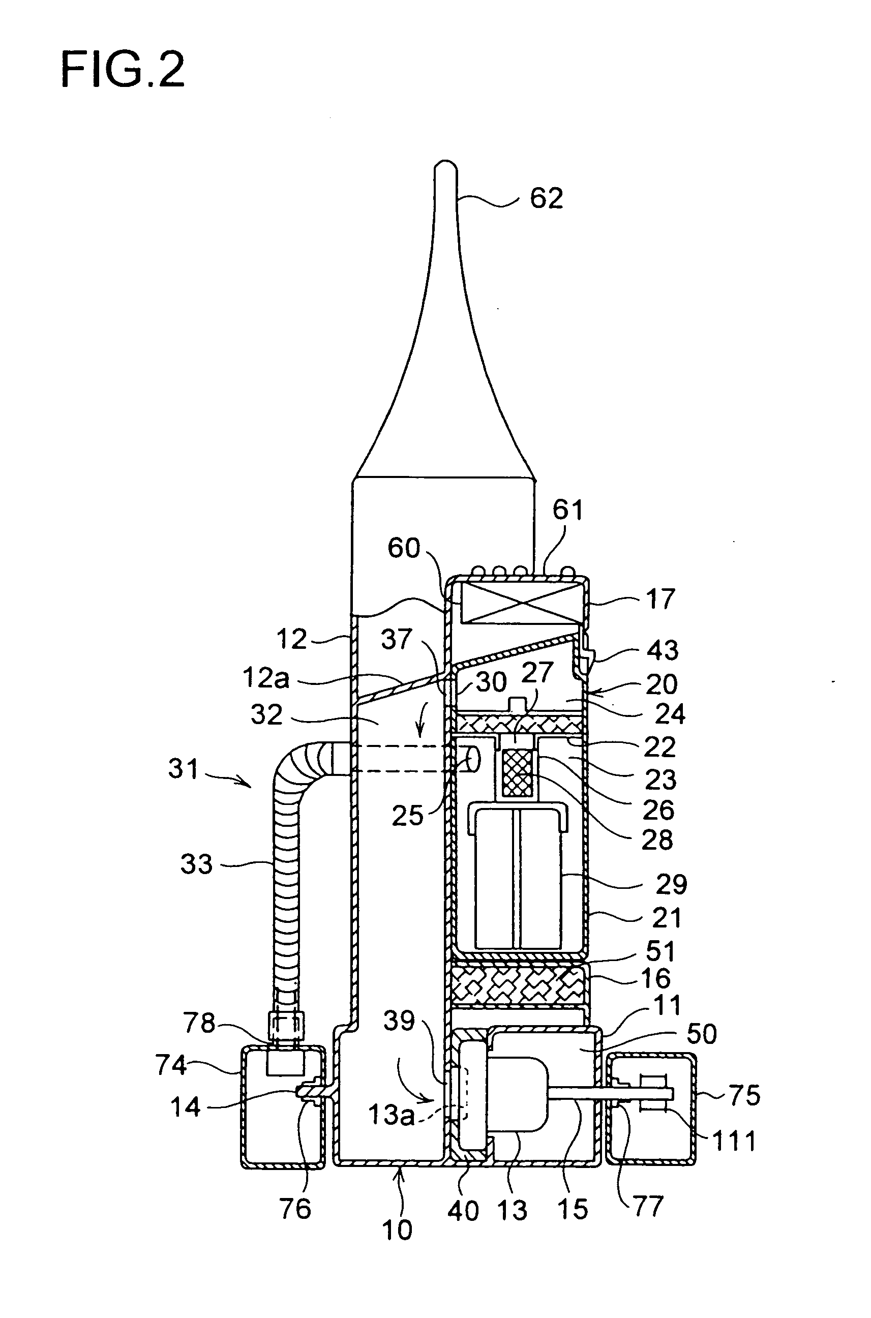
[0044] Hereinafter, the construction of the suction cleaner 1 of the invention will be described with reference to FIGS. 1 to 9. In the following descriptions of the construction of the suction cleaner 1, the directions are defined as follows: assuming that the suction cleaner 1 is placed in front of a user, who is thus standing behind the suction cleaner 1 so as to operate it from behind, the side of the suction cleaner 1 at which the user is standing is referred to as the rear side of the suction cleaner 1, and the side opposite thereto is referred to as the front side of the suction cleaner 1; when the suction cleaner 1 is observed from the front side thereof, the side thereof located at the same side as the observer's left hand is referred to as the left-hand side of the suction cleaner 1, and the side opposite thereto is referred to as the right-hand side of the suction cleaner 1.

[0045] The suction cleaner 1 is of an upright type, and divides roughly into two parts, namely a cl...

second embodiment

[0123] In the second embodiment, coaxially with the pivot portion 152 of the fork 150 is arranged a rotary operation member 152b. The pivot portion 152 of the fork 150 and the rotary operation member 152b can be arranged coaxially by pivoting the rotary operation member 152b on the shaft 142. The rotary operation member 152b is located behind the pivot portion 152. The rotary operation member 152b and the lever 154 are provided on the part of the rotary operation member 152b. Between the rotary operation member 152b and the frame 141 is arranged an unillustrated toggle spring for crispy switching of the rotary operation member 152b between different angles.

[0124] Between the rotary operation member 152b and the pivot portion 152 is provided an engaging means 170. The engaging means 170 is composed of a projection 171 that protrudes from the rotary operation member 152b to overhang the outside of the pivot portion 152 and a projection 172 that protrudes from the outer circumference o...

third embodiment

[0138] In the third embodiment, the crank 161 has a circular cross-section in the central portion thereof where it is pivoted by the bearings 162, but has the bent portions at both ends thereof formed flat. Moreover, the crank 161 has, in a portion thereof on the side of the belt shifting device 120, a separately formed metal member, composed of an end 161b and an arm 161c, welded thereto so as to have a shape as shown in the figures. To obtain higher strength, it is preferable to bend the crank 161 while it still has a circular cross-section throughout and thereafter form the ends thereof flat, rather than bending already flattened portions thereof.

[0139]FIG. 13 shows the state of the coordinating means 160 as observed when the first suction mouth 81 is selected. The front portion of the pedal 180 is lifted up, and the link 184 presses frontward the arm 161c of the crank 161. The end 161a of the crank 161 presses down the front portion of the lever 132. This causes the switch valve...


PUM


Abstract

A suction cleaner that sucks in dust, from a suction mouth of a suction mouth body, with airflow generated through operation of an electric air blower and introduces the sucked airflow into a dust collection device to collect the dust. The suction mouth body is provided with a first suction mouth and a second suction mouth. An agitator is arranged at the first suction mouth. The first suction mouth is selected by a suction mouth-switching device, and the agitator is driven when the suction is carried out from the first suction mouth. A mechanism for transmitting power to the agitator includes a driving pulley that co-rotates with the agitator, an idler that can be rotated independently of the agitator, and a belt that is shifted between the driving pulley and the idler by a belt-switching device.

Description

TECHNICAL FIELD [0001] The present invention relates to a suction cleaner, and particularly to the construction of the suction mouth portion thereof. BACKGROUND ART [0002] A suction cleaner sucks in, along with an air stream produced as an electric blower is operated, dust through a suction mouth, and then introduces the air stream thus sucked in into a dust collecting device to collect the dust. These days, for houses fitted with carpets, many suction cleaners are, at their suction mouth, provided with an agitator for raking dust off a carpet. Examples of suction cleaners provided with an agitator are disclosed in Japanese Patent Applications Laid-Open Nos. S61-191329 and H8-164095. An example of a device for switching whether or not to drive an agitator is disclosed in Japanese Patent Application Laid-Open No. H6-154134. [0003] An suction cleaner provided with an agitator at its suction mouth is not necessarily fit for all types of floor. Operating an agitator on a floor laid with...

Claims


Application Information

Patent Timeline
Patent Type & Authority Applications(United States)
IPC IPC(8): A47L5/28A47L5/30A47L9/04
CPCA47L5/30A47L9/0444A47L9/0411
Inventor YOSHIMURA, HIROSHINISHINAKA, NOBORUHAMADA, SUSUMU
Owner SHARP KK
Why Eureka
Try Eureka