Control knob of the retractable type with slowed-down extraction, in particular for an electrical household appliance

a technology of slowed-down extraction and control knob, which is applied in the direction of mechanical control devices, wing knobs, instruments, etc., can solve the problem that the known device of slowing down extraction cannot be applied to the control knob of electrical household appliances, and achieve the effect of slowing down the motion of extraction

Inactive Publication Date: 2005-02-24
ITW IND COMPONENTS SRL
View PDF8 Cites 21 Cited by
  • Summary
  • Abstract
  • Description
  • Claims
  • Application Information

AI Technical Summary

Benefits of technology

[0008] In this way, when the cup-shaped grip, which constitutes the part of knob that is visible and can be actuated by the user, (the rest of the knob being in use housed in a front seat of the household appliance) is pushed by the spring towards the extracted position (from the aforesaid seat), its motion of extraction from the seat, which entails a relative sliding with respect to the hub, brings about an increase in the volume...

Problems solved by technology

However, known devices for slowing down extraction cannot be applied to control knobs of electrical household appliance...

Method used


Image

  • Control knob of the retractable type with slowed-down extraction, in particular for an electrical household appliance
  • Control knob of the retractable type with slowed-down extraction, in particular for an electrical household appliance

Examples


Embodiment Construction

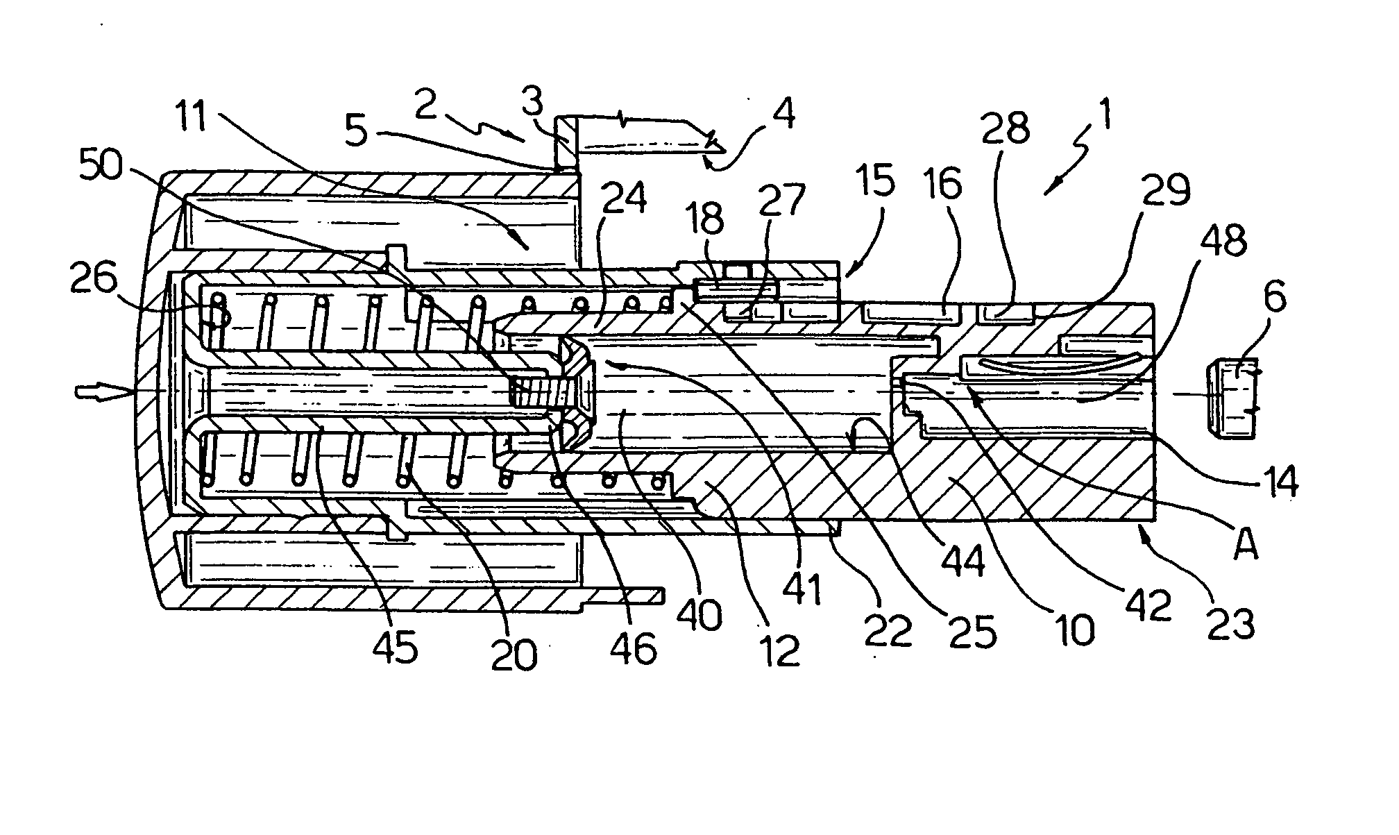
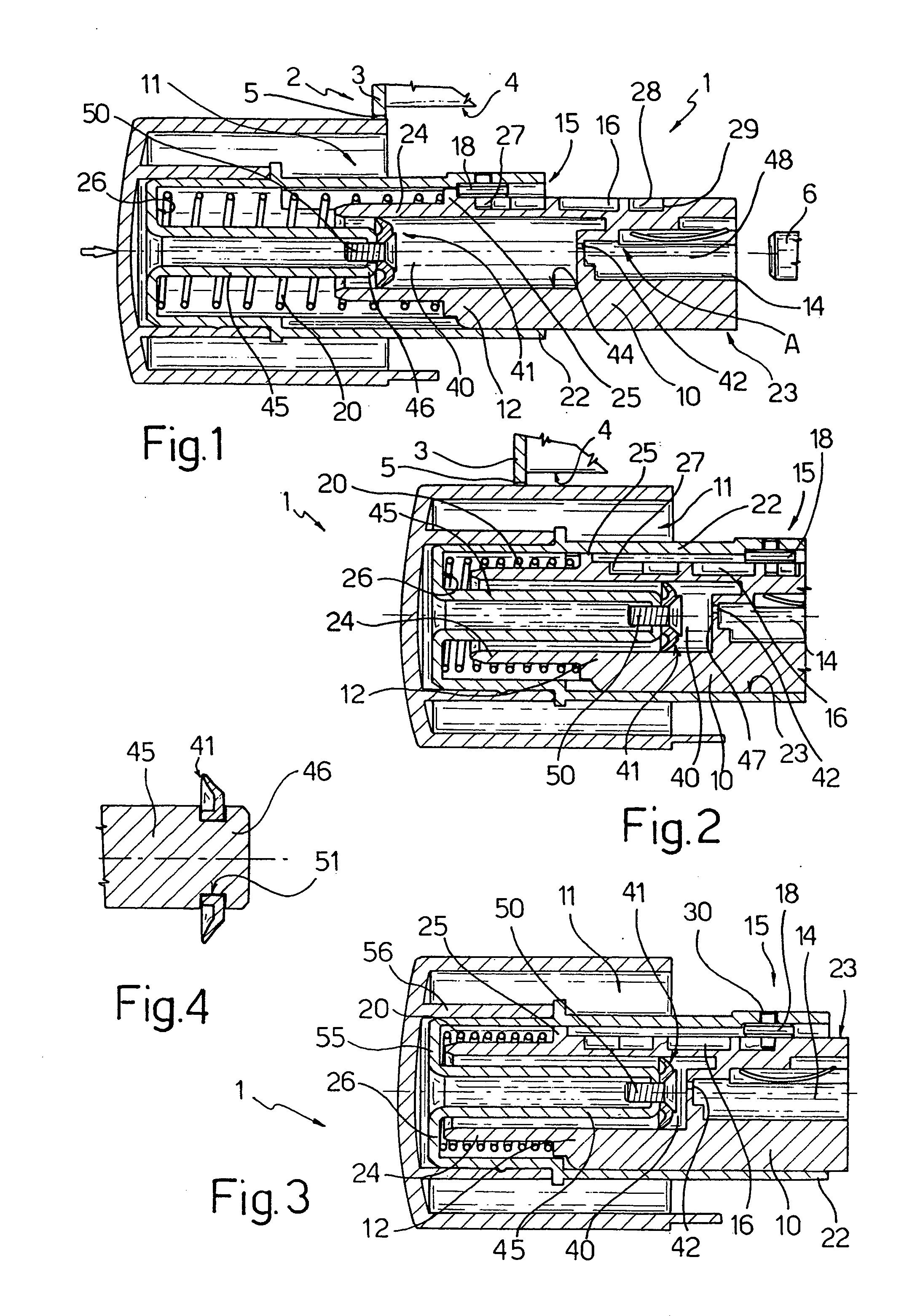
[0013] With reference to FIGS. 1 to 3, reference number 1 indicates, as a whole, a control knob of the retractable type for an electrical household appliance 2 of a known type (for example a washing machine, a dish washer, or an oven), of which, for reasons of simplicity, there is illustrated in exploded view only a portion of a body 3, which is provided, generally in the area known as “front panel”, with a seat that is open at the front 4 for housing the knob 1, within which there is set, on the opposite side of a front mouth 5 of the seat 4, a rotatable control pin 6 of the household appliance, of a known type, designed to control, according to its own angular position, at least one function of the household appliance (for example, a washing or cooking program, a washing or cooking temperature, etc.)

[0014] The knob 1 comprises a hub 10, having a substantially cylindrical symmetry, which can be connected angularly, in use, within the seat 4, with pin 6, and a grip 11, which is car...


PUM


Abstract

Described herein is a knob including: a hub, which can be connected so that it is angularly fixed in a seat open at the front of an electrical household appliance, with a rotatable control pin of the household appliance designed to control, according to its own angular position, at least one function of the household appliance; a grip, which is carried so that it is angularly fixed but can slide axially, against the action of elastic means, on a first end of the hub opposite to a second end thereof for connection with said pin; and means for selective axial connection of the grip to the hub designed to block the grip in a first axial position, in which the grip projects in cantilever fashion from the first end of the hub and is set, in use, at least partially on the outside of said seat, and in a second axial position, in which the grip is fitted on said hub and is, in use, retracted within said seat; between the grip and the hub there being defined a closed chamber having a variable volume that is a function of the axial position of the grip on the hub and there being provided sliding seal means for sealing said air-tight chamber, and a calibrated restriction for connecting the inside of said chamber with the external environment in such a way as to bring about a negative pressure in said chamber as a result of the movement of the grip towards the first axial position.

Description

[0001] The present invention relates to a control knob of the retractable type for electrical household appliances, otherwise known as “push-push” knob, wherein the grip thereof is slowed down in its motion of extraction from the seat for housing the knob on the household appliance. BACKGROUND OF THE INVENTION [0002] It is known that, in all types of electrical household appliances (washing machines, dish washers, ovens, etc.) the control knob or knobs for controlling the various functions of the household appliance (for example, washing or cooking programs, temperature of the water, etc.) are controlled via rotatable grips. With increasing frequency said knobs are of the “retractable” type, in general obtained via a so-called “push-push” mechanism of a known type, which can be retracted into a purposely provided housing seat open at the front of the household appliance, for example made on the front panel, both for the purpose of reducing the overall dimensions and purely for reaso...

Claims


Application Information

Patent Timeline
IPC IPC(8): H01H3/08H01H3/60
CPCH01H3/08H01H3/60H01H2003/085Y10T74/2084Y10T16/473Y10T16/506Y10T16/509
Inventor CHIRUMBOLO, DINO
Owner ITW IND COMPONENTS SRL
Why Eureka
Try Eureka