
Image forming apparatus

a technology forming device, which is applied in the direction of electrographic process apparatus, thin material processing, instruments, etc., can solve the problems of difficult work of jam treatment, difficult work of image forming apparatus, and often occurring jamming in the vicinity of manual paper feeding device, etc., and achieves easy work and less labor.

Inactive Publication Date: 2005-02-24
KK TOSHIBA +1
View PDF4 Cites 13 Cited by
  • Summary
  • Abstract
  • Description
  • Claims
  • Application Information

AI Technical Summary

Benefits of technology

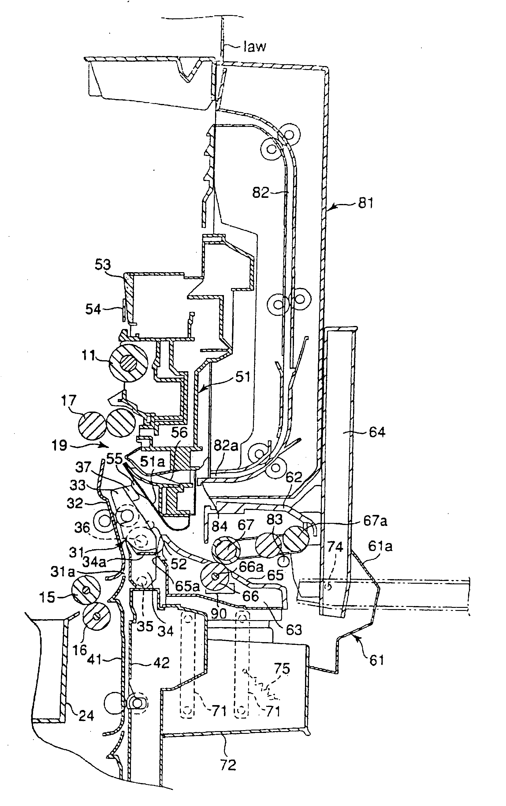
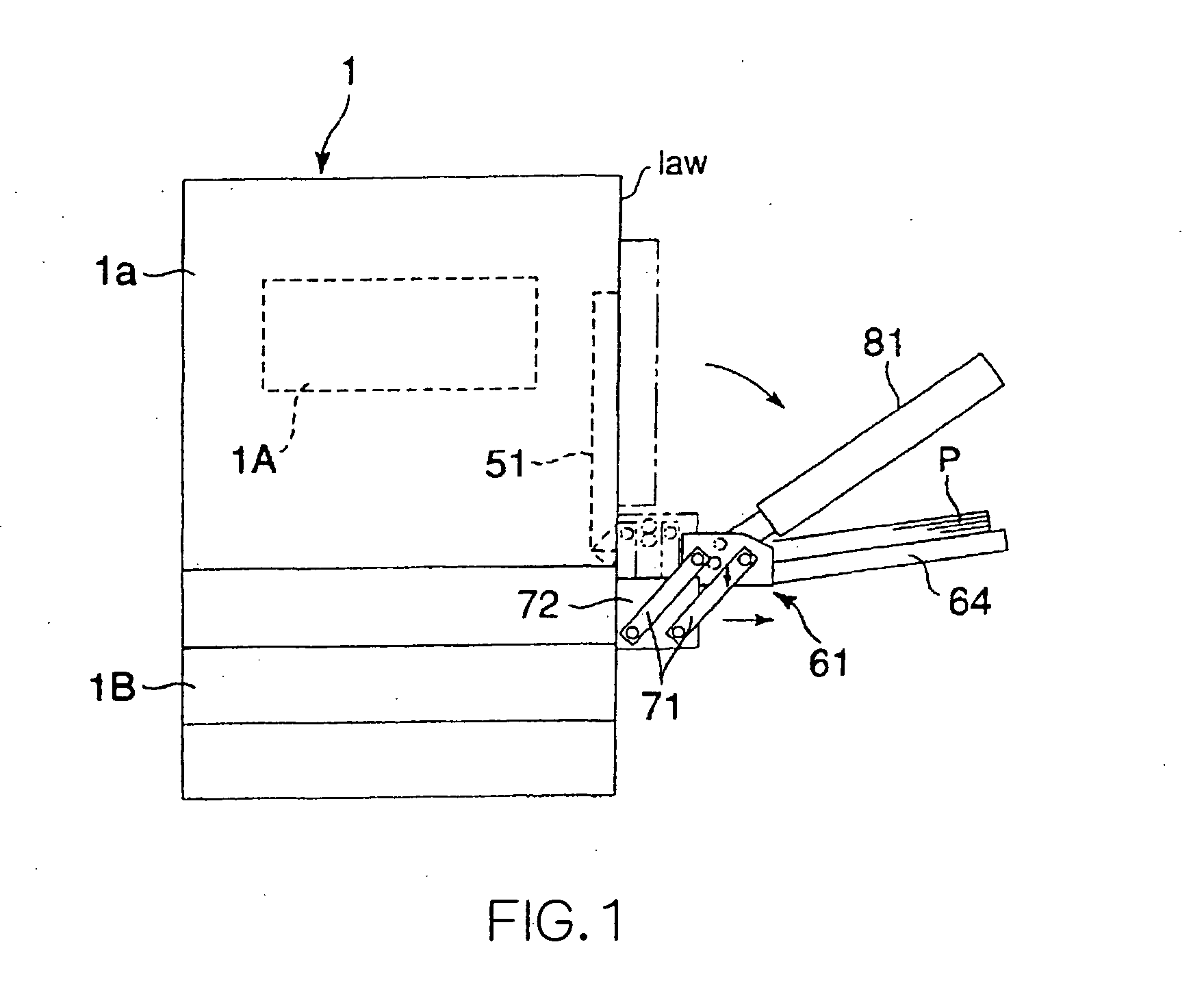
[0010] It is an object of the present invention to provide an image forming apparatus for easily removing paper jammed in the vicinity of a manual paper feeding device, while being the structure equipped with an automatic double-side unit and a manual paper feeding device.
[0013] Therefore, the jammed paper can be removed easily from an area in the vicinity of the manual paper feeding device with less labor and under the circumstances that work is done easily, such that paper not sandwiched between the delivery portion and the separation portion of the manual paper feeding device is removed through an open space between the manual paper feeding device and the apparatus body.

Problems solved by technology

Incidentally, in the image forming apparatus, jamming often occurs in the vicinity of the manual paper feeding device.
In the jam treatment in the vicinity of the manual paper feeding device, work of the jam treatment is difficult because the manual paper feeding device is located in an area for carrying out work for removing the jammed sheets.
Due to the presence of the automatic both-side unit, it is difficult for the image forming apparatus having the automatic double-side unit to apply the structure for facilitating removal of the jammed manual paper in association with the opening and closing cover as in the above-described publication.
Particularly, it is hard to find the jammed paper around the manual paper feeding device.
Moreover, since the opened portions are not many, it is difficult to secure the work space for carrying out the jam treatment.
In addition, there is demanded the work which is troublesome and requires labor, such that the paper sandwiched between the paper feeding roller and the separation roller of the manual paper feeding device is pulled out, and therefore the jam treatment was considerably troublesome.

Method used


Image

  • Image forming apparatus
  • Image forming apparatus
  • Image forming apparatus

Examples


Embodiment Construction

[0021] The present invention will be described hereinafter on the basis of one embodiment shown in FIGS. 1 to 7.

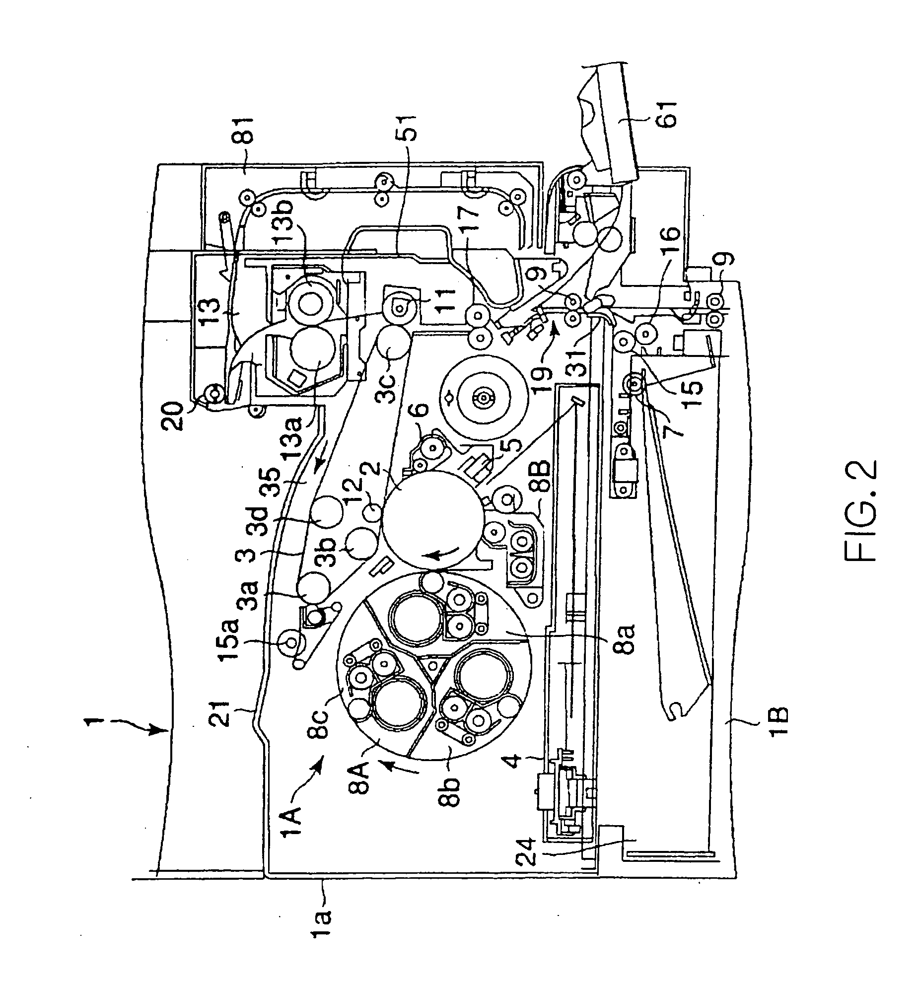
[0022] In FIGS. 1 and 2, reference numeral 1a denotes the copying machine body as the apparatus body provided on an image forming apparatus, for example, an electro-photographic copying machine 1. An image forming section 1A is encased in the upper portion of the copying machine body 1a, and a paper feeding section 1B having a plurality of paper feeding cassettes 24 is provided in the lower portion of the copying machine body 1a.

[0023] The image forming section 1A will be described with reference to FIG. 2 showing the internal construction of the copying machine body 1a.

[0024] A photosensitive drum 2 as an image carrier is rotatably provided within the copying machine body 1a. Around the photosensitive drum 2 are disposed, along the rotational direction thereof, a charging unit 5 for charging the surface of the photosensitive drum 2 to a prescribed potential, a developi...


PUM


Abstract

The present invention provides an image forming apparatus in which an automatic double-side unit 81 is provided free to open and close on the side of an apparatus body 1a, and a manual paper feeding device 61 is provide adjacent to the automatic double-side unit. And, there are provided manual moving mechanisms 75, 86, 86a for moving the manual paper feeding device in a direction away from the side of the apparatus body in association with opening operation of the automatic double-side unit. Further, there is provided a pressure contact release mechanism 90 for releasing pressure contact between a paper feeding roller 67 and a separation roller 66 of the manual paper feeding device in association with opening operation of the automatic double-side unit, whereby when the automatic double-side unit is operated to be opened, an open portion is formed between the manual paper feeding device and the apparatus body in association therewith so as to release restriction of paper sandwiched between the paper feeding roller and the separation roller of the manual paper feeding device.

Description

BACKGROUND OF THE INVENTION [0001] 1. Field of the Invention [0002] The present invention relates to an image forming apparatus provided with an automatic double-side unit for reversing paper and a manual paper feeding device. [0003] 2. Related Art Statement [0004] In the image forming apparatus, there is an apparatus having a double-side printing function and a manual printing function. This image forming apparatus has the structure that in order to install machines and tools having both functions utilizing a limited space, an automatic double-side unit (ADU) for reversing paper in order to perform double-side printing is mounted on the side of the apparatus body encasing an image forming section, and a manual paper feeding device is mounted adjacent to the apparatus under the automatic double-side unit in order to perform printing by manual paper feeding. [0005] Incidentally, in the image forming apparatus, jamming often occurs in the vicinity of the manual paper feeding device. [...

Claims


Application Information

Patent Timeline
IPC IPC(8): G03G15/00B65H11/00B65H29/66B65H85/00G03G15/23G03G21/16
CPCG03G15/232G03G21/1638G03G2221/1675
Inventor MURAKAMI, REIJIKODO, MASAHIRO
Owner KK TOSHIBA
Learn More