Undercarriage flow control device and method for reducing the aerodynamic drag of ground vehicles

Inactive Publication Date: 2005-02-24
WOOD RICHARD M
View PDF0 Cites 31 Cited by
  • Summary
  • Abstract
  • Description
  • Claims
  • Application Information

AI Technical Summary

Benefits of technology

[0056] (s) to provide a means to improve the safety of nearby vehicles;
[0057] Further objects and advantages are to provide a device that can be easily and conveniently used to minimize aerodynamic drag on an

Problems solved by technology

The wake flow of a bluff-base ground vehicle produces high drag forces on the parent vehicle, large interference effects on other vehicles in close proximity, water spray and instability in brak

Method used


Image

  • Undercarriage flow control device and method for reducing the aerodynamic drag of ground vehicles
  • Undercarriage flow control device and method for reducing the aerodynamic drag of ground vehicles
  • Undercarriage flow control device and method for reducing the aerodynamic drag of ground vehicles

Examples


Example

[0077] The following descriptions are of exemplary embodiments of the invention only, and are not intended to limit the scope, applicability or configuration of the invention in any way. Rather the following description is intended to provide a convenient illustration for implementing various embodiments of the invention. As will become apparent, various changes may be made in the function and arrangement of the elements described herein without departing from the spirit and scope of the invention. For example, though not specifically described, many shapes, widths, leading edge shapes, spacing and orientation of the undercarriage flow control surfaces, candidate vehicles that can benefit from the device, fabrication means and material, attachments means and material should be understood to fall within the scope of the present invention.

[0078] Referring now in detail to the drawings, like numerals herein designate like numbered parts in the figures.

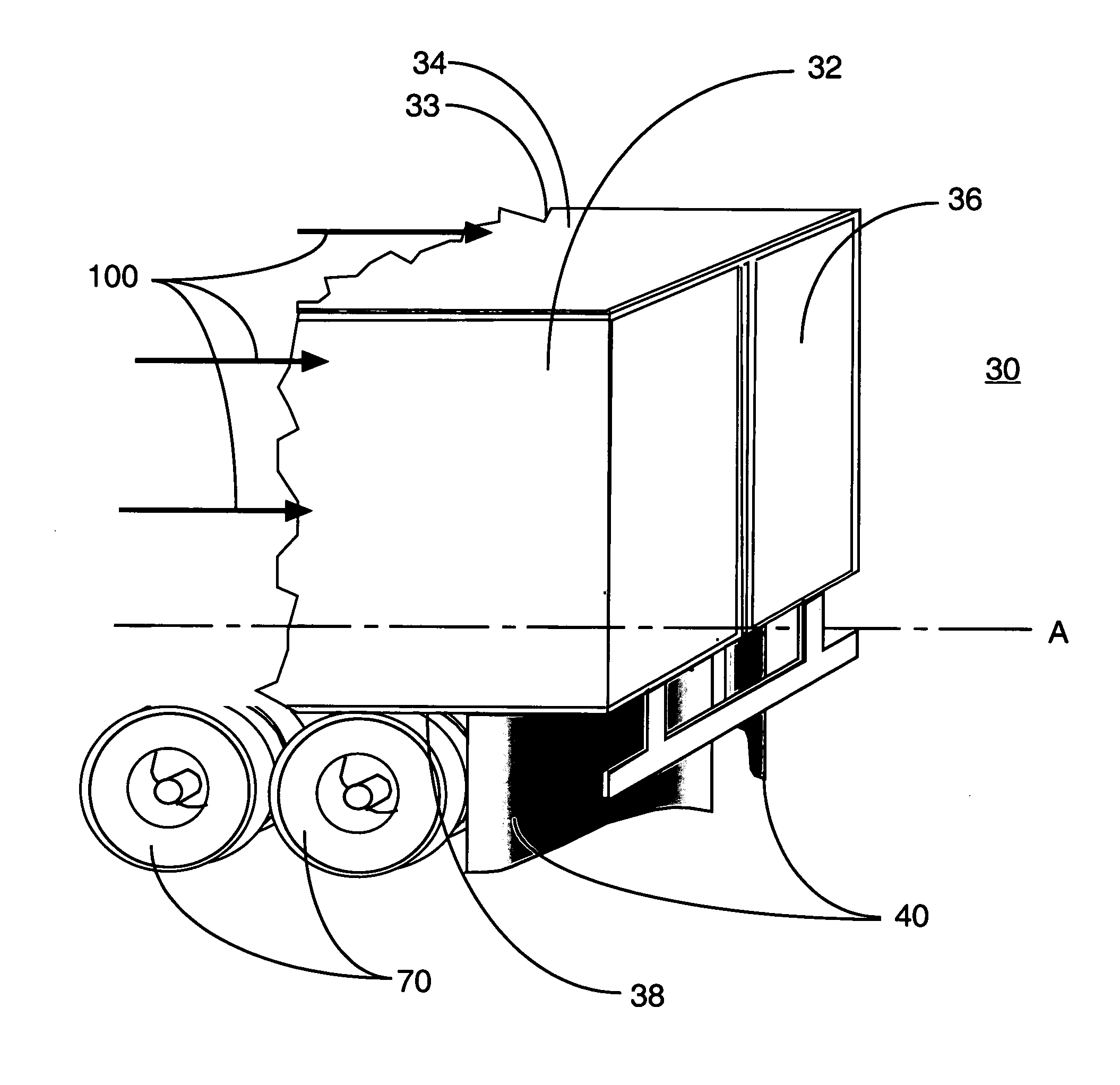
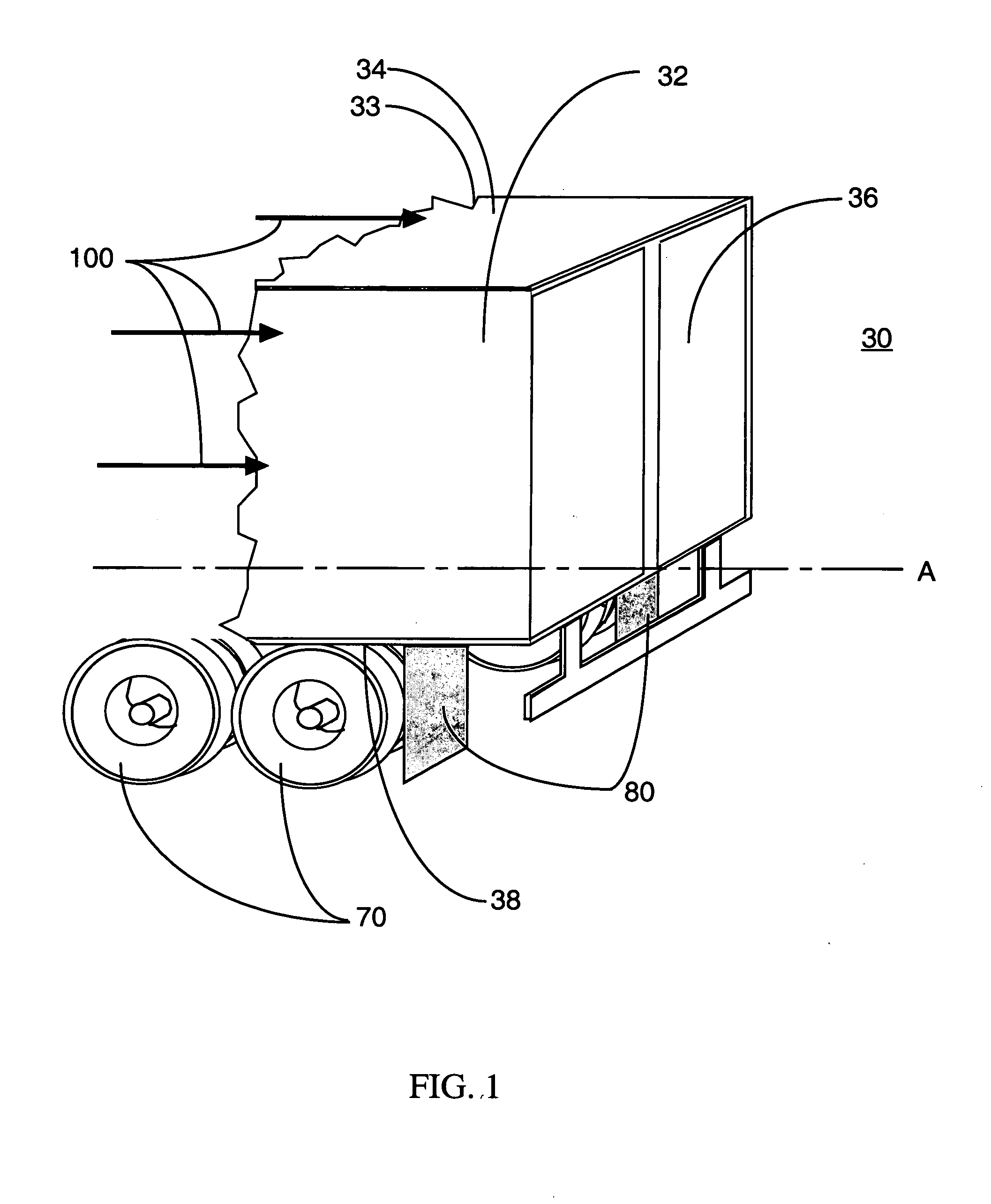
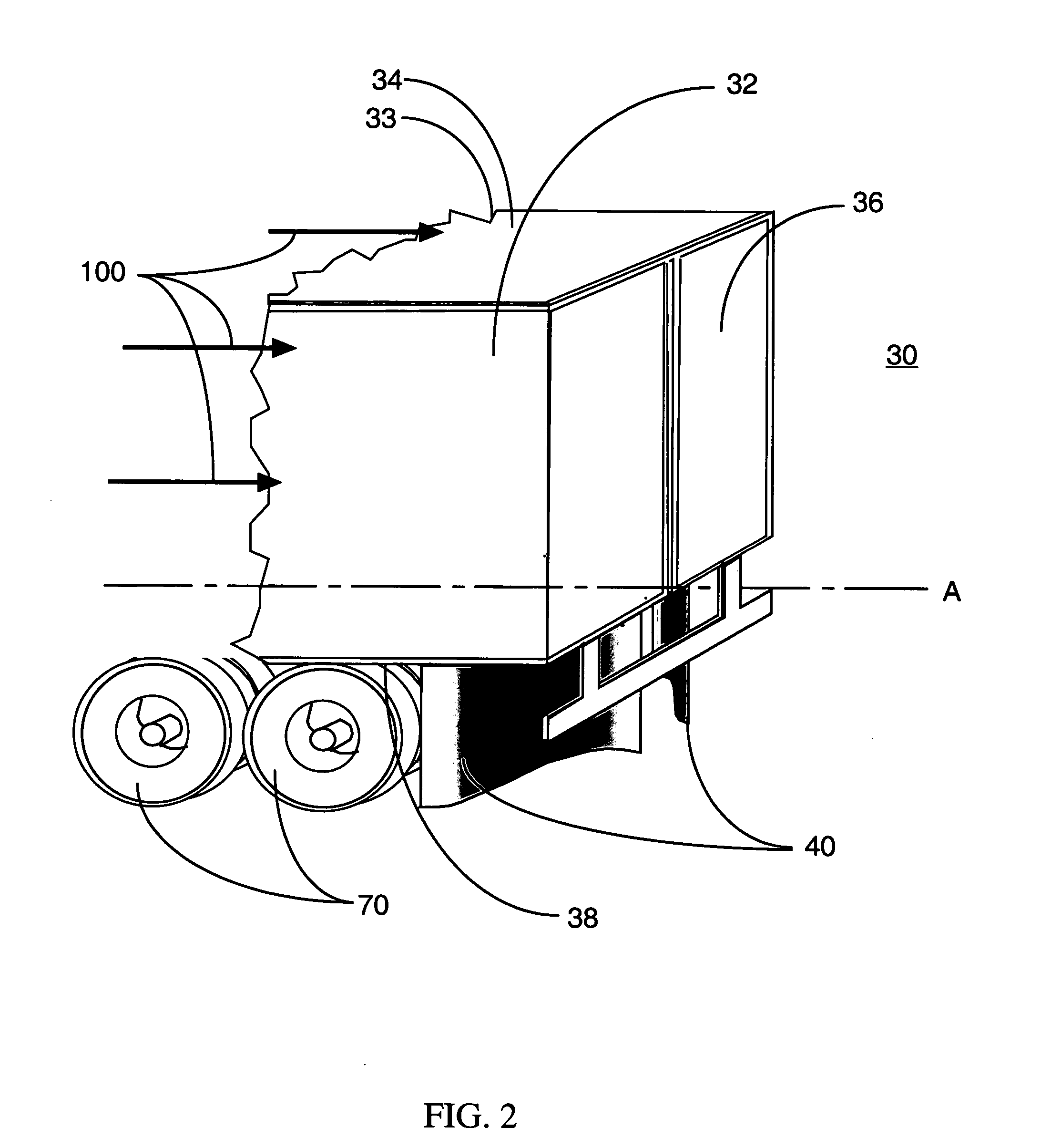
[0079]FIG. 1 is a rear perspecti...


PUM


Abstract

An improved method and device for the reduction of aerodynamic drag and for improved performance of ground vehicles by increasing the pressure on the base area of a bluff-base ground vehicle or vehicle component by conditioning the undercarriage flow and controlling the discharge of the undercarriage flow into the trailing wake of a ground vehicle. The subject invention provides an improved method and device for generating a reduction in the drag force on a bluff-base object moving through air. The apparatus consists of aerodynamically shaped surfaces that are attached to the undercarriage of a vehicle between the base area and the aft most set of wheels. The surfaces are shaped and positioned such that they may be combined with the vehicle lower surface and the ground to form a nozzle with the smallest opening located at the aft end of the vehicle and the largest opening located forward of the smallest opening. The largest opening has a width that is equivalent to the width of the vehicle and has a height that is approximately equal to the distance between the vehicle lower surface and the ground. The smallest opening is located at the base of the vehicle and has an area and shaped opening to maximize the discharge of the undercarriage flow into the wake. The surfaces that comprise the invention are aerodynamically shaped to minimize separation of the flow passing through the device and on the outer surface of the device and at the same time, to increase the momentum for the flow passing through the device and to entraining additional air externally to the device. The reduction in drag force results from the increase in pressure acting on the base area of the vehicle. The increase in base pressure is a result of the increase in wake energy and reduction in the unsteady wake flow due to the addition of the high momentum undercarriage flow into the wake. The objects and advantages also extend to other applications in which an object or vehicle is moving through either a gas or fluid.

Description

CROSS-REFERENCE TO RELATED APPLICATIONS [0001] This application claims a previous provisional patent application, No. 60 / 496,852 with a filing date of Aug. 21, 2003 and entitled “Undercarriage flow control device and method for reducing the aerodynamic drag of ground vehicles”.ORIGIN OF THE INVENTION [0002] The invention described herein was made by employees of the United States Government, and may be manufactured and used by or for the Government without payment of any royalties thereon or therefore.REFERENCE TO SEQUENCE LISTING, A TABLE, OR A COMPUTER PROGRAM LISTING COMPACT DISK APPENDIX [0003] Not applicable. BACKGROUND [0004] 1. Field of Invention [0005] The invention relates to the reduction of aerodynamic drag for moving ground vehicles; specifically to an improved method and device for the reduction of aerodynamic drag and for improved performance of ground vehicles by increasing the pressure on the base area of a vehicle or vehicle component by controlling the wake flow of...

Claims


Application Information

Patent Timeline
IPC IPC(8): B62D25/16B62D35/00B62D35/02
CPCB62D25/168B62D35/02B62D35/001Y02T10/88
Inventor WOOD, RICHARD M.
Owner WOOD RICHARD M
Why Eureka
Try Eureka