
Brake control apparatus

Active Publication Date: 2005-02-24
ADVICS CO LTD
View PDF1 Cites 13 Cited by
  • Summary
  • Abstract
  • Description
  • Claims
  • Application Information

AI Technical Summary

Benefits of technology

[0007] It is therefore an object of the present invention to provide a brake control apparatus which is capable of preventing a driver from feeling uncomfortable with braking and of offering a smooth braking feeling.
[0008] In a first aspect of the present invention, based on a first target deceleration determined in accordance with the amount of operation of a brake operating member, limit values of deceleration increasing and decreasing gradients with respect to the first target deceleration are set. Based on the limit values, a second target deceleration is obtained by correcting the first target deceleration. Accordingly, the deceleration increasing / decreasing gradient becomes small when braking is gentle. This makes it possible to lessen the sharp change in brake force to allow smooth brake control. Further, the deceleration increasing / decreasing gradient becomes large when braking is abrupt. This makes it possible to increase the change in the brake force to provide a high response.

Problems solved by technology

Further, the deceleration increasing / decreasing gradient becomes large when braking is abrupt.

Method used


Image

  • Brake control apparatus
  • Brake control apparatus
  • Brake control apparatus

Examples


first embodiment

[0024] First Embodiment

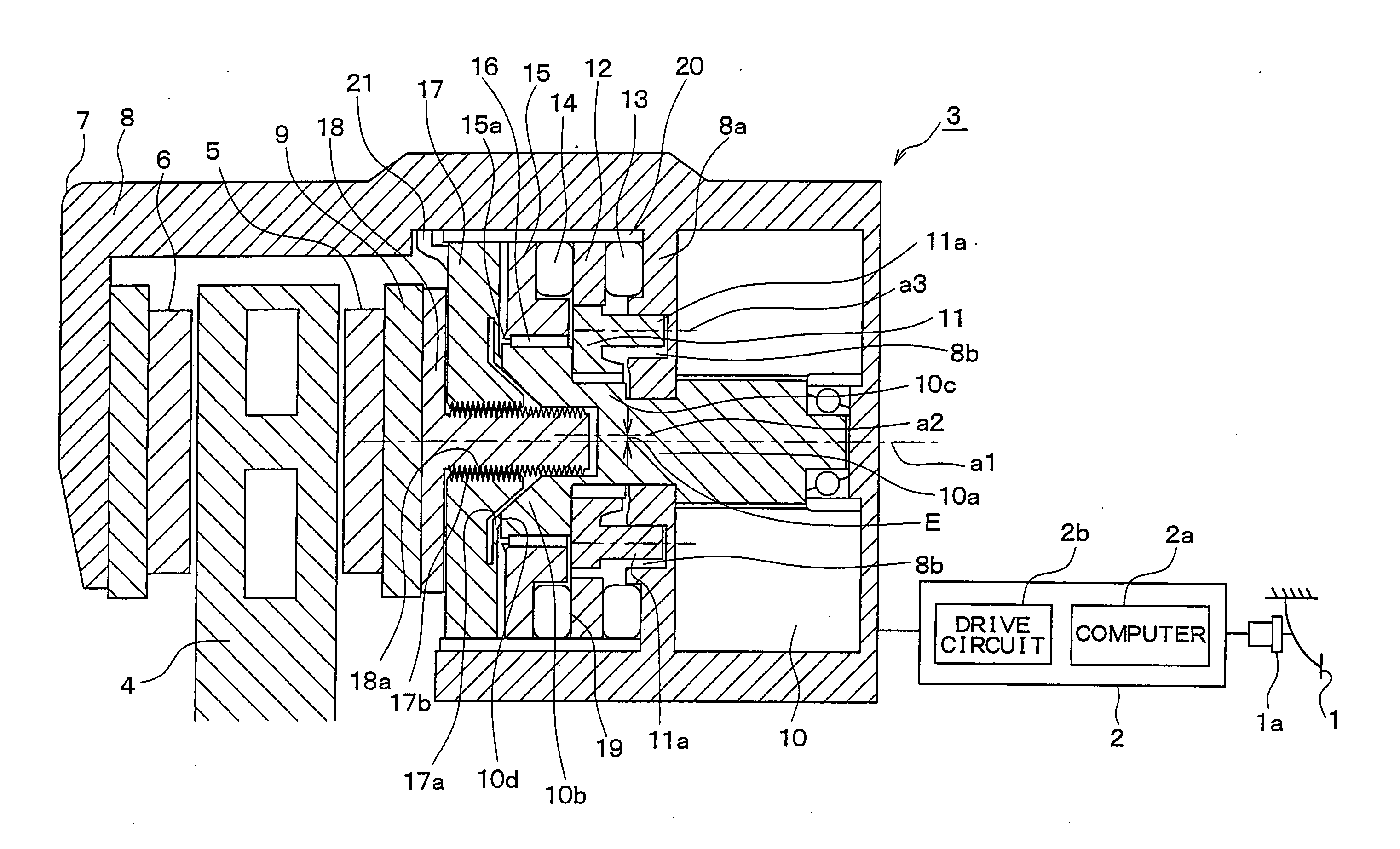
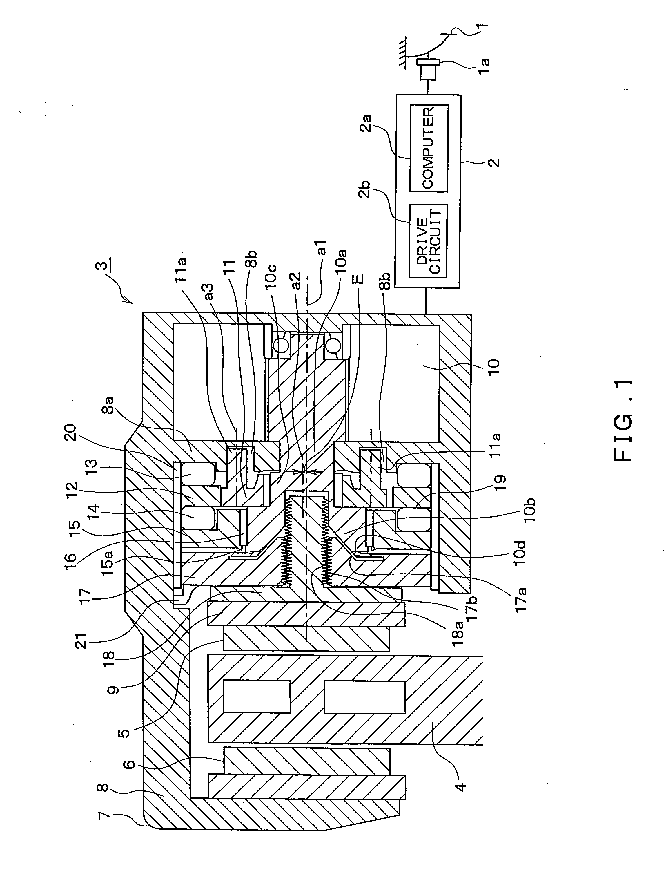
[0025]FIG. 1 illustrates a rough outline of the structure of an electric brake system to which an embodiment according to the present invention is applied. The structure of the electric brake system will be described below with reference to FIG. 1.

[0026] The electric brake system includes a brake pedal 1 corresponding to a brake operating member, an electronic control unit (hereinafter referred to as “ECU”) 2, an electric brake 3 for generating a braking force on each wheel, and the like. The electric brakes 3 are mounted individually on the four wheels, but FIG. 1 representatively illustrates only the electric brake 3 mounted on one of the four wheels.

[0027] To the brake pedal 1, a pedal operating sensor 1a is attached for detecting the amount of operation of the brake pedal 1, e.g., the pedal depression force or the amount of stroke. A detection signal is sent from the pedal operating sensor 1a to the ECU 2.

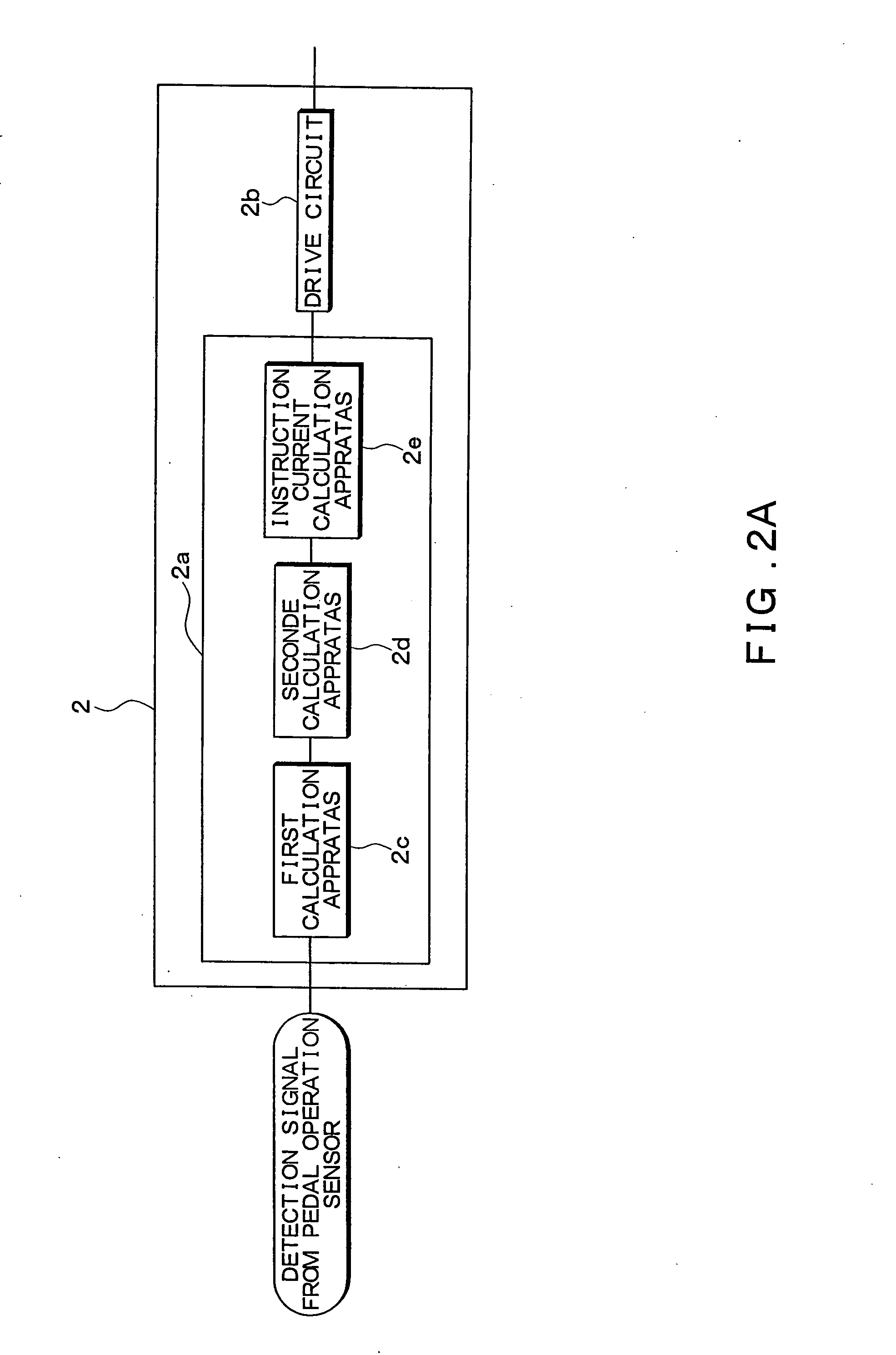
[0028] The ECU 2 is equipped with a computer 2a,...


PUM


Abstract

The brake control apparatus sets a target deceleration 1 in accordance with an amount of operation of the brake pedal. It calculates another target deceleration 2 on the basis of the target deceleration 1. In this calculation, limit values of deceleration increasing and decreasing gradients with respect to the target deceleration 1 are set on the basis of the target deceleration 1, and then the target deceleration 2 is obtained by correcting the target deceleration 1 on the basis of the established deceleration increasing and decreasing gradients. Accordingly, the deceleration increasing / decreasing gradient becomes small when braking is gentle. This makes it possible to curb an abrupt change in brake force to achieve smooth brake control. Further, the deceleration increasing / decreasing gradient becomes larger when braking is abrupt. Accordingly, it is possible to create a great change in brake force to provide a high response.

Description

CROSS REFERENCE TO RELATED APPLICATION [0001] This application is based upon and claims the benefit of Japanese Patent Application No. 2003-297461 filed on Aug. 21, 2003, the content of which are incorporated herein by reference. FIELD OF THE INVENTION [0002] The present invention relates to a brake control apparatus for electrically controlling brake pressure in accordance with an amount of operation of a brake pedal. BACKGROUND OF THE INVENTION [0003] In some conventional brake control apparatuses equipped with a brake-pressure generator for producing a brake force and a pedal-reaction-force generator for producing a pedal reaction force in accordance with the pedal stroke, hysteresis is incorporated in the characteristics of the brake-pressure generator and the characteristics of the pedal-reaction-force generator. By means of such incorporation of hysteresis, the brake force corresponding to the amount of operation of the brake pedal is changed in the direction of applying the b...

Claims


Application Information

Patent Timeline
IPC IPC(8): B60T8/32B60T7/04B60T8/172B60T13/66B60T13/74
CPCB60T7/042B60T8/172B60W2520/105B60T13/741B60T8/3255
Inventor YOKOYAMA, TAKAHISAARAKAWA, HARUOTAKESHITA, TAKAYUKI
Owner ADVICS CO LTD
Learn More