Dental apparatus

a technology of dental equipment and teeth, applied in the field of dental equipment, can solve the problems of reducing the cutting efficiency, affecting the cutting efficiency, and spontaneously increasing the load, and achieve the effect of efficient work

Inactive Publication Date: 2005-02-24
MORITA MFG CO LTD
View PDF8 Cites 49 Cited by
  • Summary
  • Abstract
  • Description
  • Claims
  • Application Information

AI Technical Summary

Benefits of technology

With the above-mentioned configuration, the operator can carry out operation while simultaneously checking the measurement result of th

Problems solved by technology

If a root canal is bent for example, however, the load increases spontaneously even when the operator has no intention of increasing the load, and the rotation of the cutting tool stops or reverses unexpectedly.
However, the smaller the load, the lower the efficiency of the cutting.
On the other hand, if the load is increased so as to be nearly equal to the reference load torque, the cutting

Method used


Image

  • Dental apparatus
  • Dental apparatus
  • Dental apparatus

Examples


Embodiment Construction

Before the description of the preferred embodiment according to the present invention proceeds, it is to be noted that like or corresponding parts are designated by like reference numerals throughout the accompanying drawings.

A dental apparatus in accordance with the embodiment of the present invention will be described below referring to FIGS. 1 to 10.

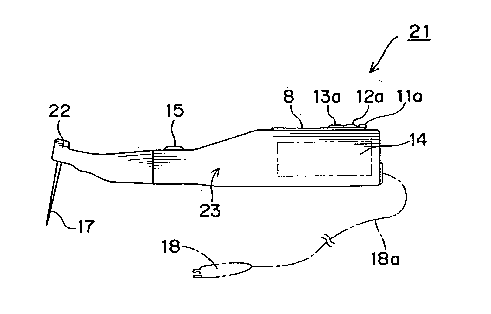
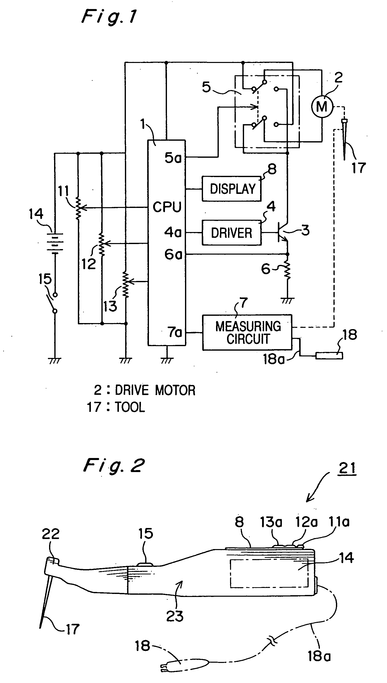
FIG. 1 is a circuit diagram of a dental apparatus in accordance with a preferred embodiment of the present invention. Reference numeral 1 designates a CPU for controlling the overall operation of the dental apparatus. Reference numeral 2 designates a motor for driving a cutting tool 17. Reference numeral 3 designates a transistor switch. Reference numeral 4 designates a driver circuit for driving the transistor switch. Reference numeral 5 designates a rotation direction selection switch. Reference numeral 6 designates a resistor for detecting a load torque. Reference numeral 7 designates a root canal length measurement circuit. Re...


PUM


Abstract

A dental equipment for cutting teeth, forming root canals and so on. The dental apparatus includes: an actuator for actuating a cutting tool; a load sensor for sensing a load worked in the cutting tool; and a load indicator for making an operator know the load sensed by the load sensor visually, aurally and/or tactily.

Description

CROSS-REFERENCE TO RELATED APPLICATION This application is based upon application No. 2001-135129 filed in Japan, the contents of which are hereby incorporated by reference. BACKGROUND OF THE INVENTION 1. Field of the Invention The present invention relates to a dental apparatus. More particularly, it relates to the dental apparatus capable of cutting teeth, forming root canals and applying to dental implant, for example, by driving a cutting tool. 2. Description of the Related Arts Conventionally, a dental apparatus wherein the rotation of its cutting tool (file) is controlled depending on the load torque applied to the cutting tool to prevent the breakage of the cutting tool when expanding a root canal, for example, has been proposed. In this dental apparatus, the cutting tool rotates reversibly or stops when the load torque reaches a reference torque or more (for example, Japanese Non-examined Patent Publication No. Hei 9-38108). If a root canal is bent for example, however...

Claims


Application Information

Patent Timeline
IPC IPC(8): A61C1/02A61C1/00A61C1/06A61C1/18A61C3/00A61C3/02A61C19/04
CPCA61C1/0015A61C1/186A61C19/042A61C19/041A61C3/00
Inventor KATSUDA, NAOKIMATOBA, KAZUNARINAKAI, TERUJI
Owner MORITA MFG CO LTD
Why Eureka
Try Eureka