Variable magnetic moment MR navigation

a magnetic moment and mr technology, applied in the field of magnetic field navigation, can solve the problems of significant heating of long electrical leads to the coils, high cost of fabricating such coils and assembling them into medical devices, etc., and achieve the effect of reducing dependen

Inactive Publication Date: 2005-02-24
STEREOTAXIS
View PDF4 Cites 108 Cited by
  • Summary
  • Abstract
  • Description
  • Claims
  • Application Information

AI Technical Summary

Benefits of technology

The present invention provides navigation in magnetic fields with reduced reliance upon, or even the complete elimination of microcoils, and their attendant problems. A preferred embodiment of a medical device constructed according to the principles of this invention comprises at least one element of a material whose magnetization can be altered by changing a physical con...

Problems solved by technology

However, it can be expensive to fabricate such coils and assemble them into the medical device.
F...

Method used


Image

  • Variable magnetic moment MR navigation
  • Variable magnetic moment MR navigation
  • Variable magnetic moment MR navigation

Examples


first embodiment

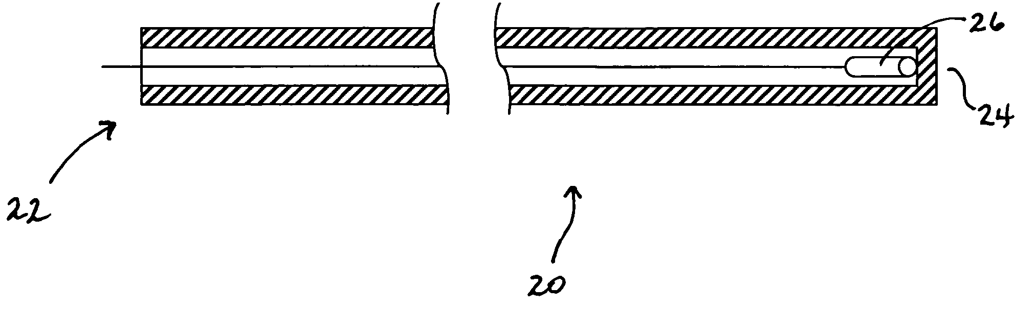
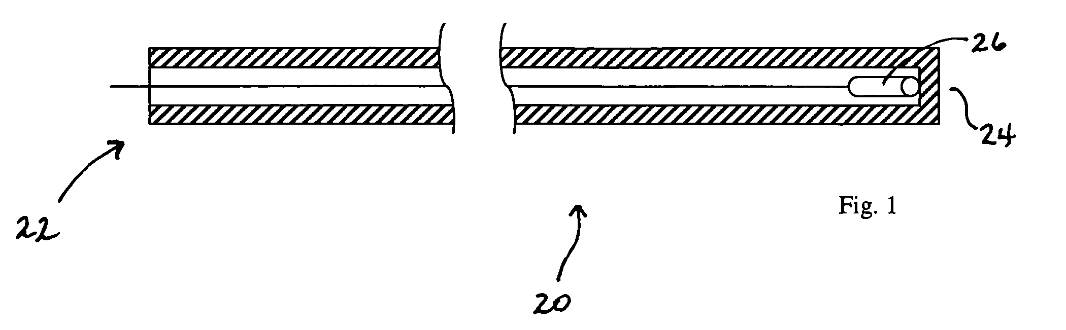
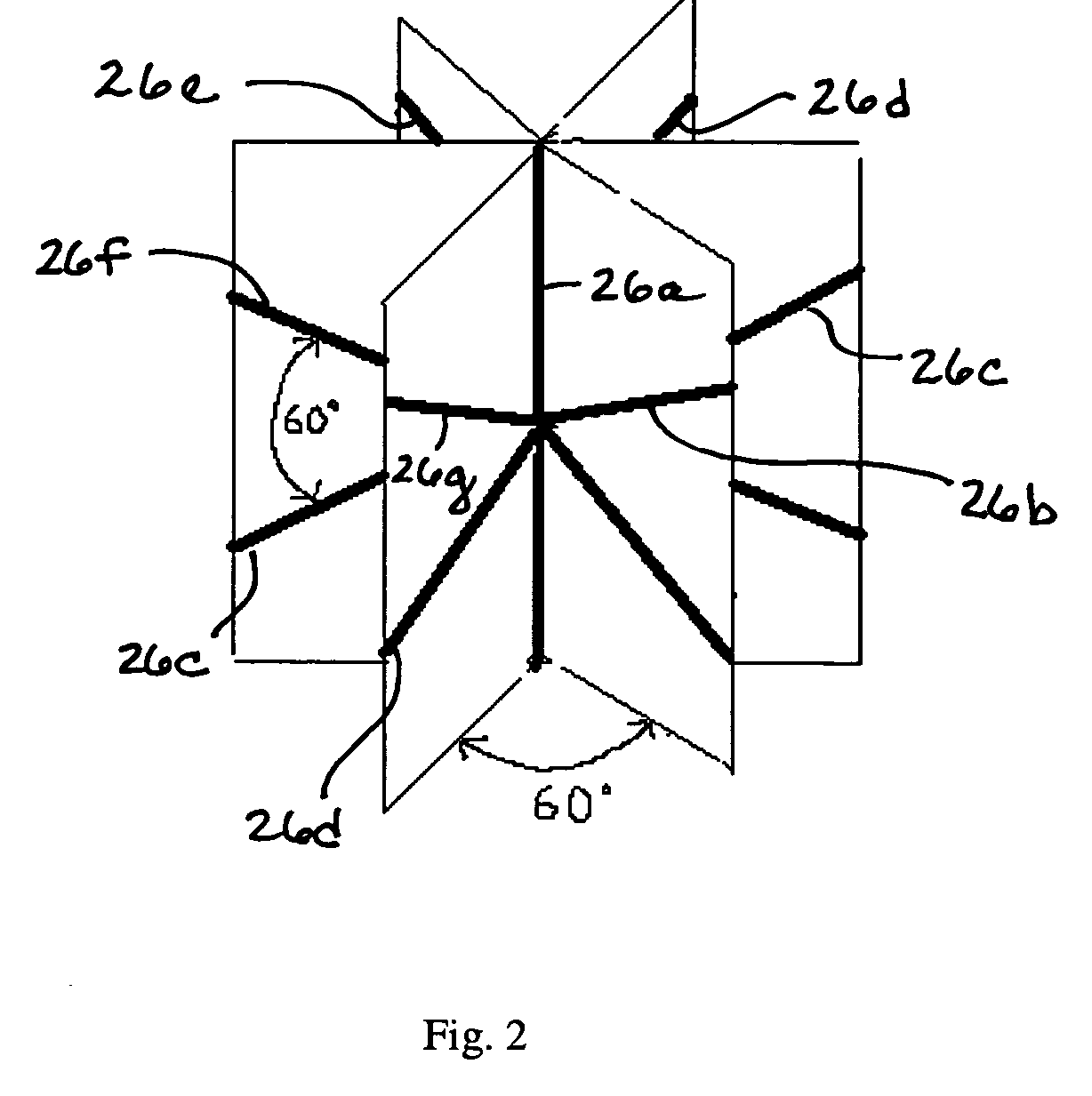
a medical device constructed according to the principles of this invention is indicated generally as 20 in FIG. 1. As shown in FIG. 1, the medical device 20 has a proximal end 22 and a distal end 24. The device 20 includes at least one, and in this preferred embodiment a plurality of, controllable magnetically responsive elements 26. One possible configuration of magnetically responsive elements 26 is shown in FIG. 2. As shown in FIG. 2, seven elements 26a-26g are arranged in the distal end of the medical device, with a maximum angular spacing of 60°.

While variable current flowing in a coil generates a variable magnetic moment, various embodiments of the present invention can include alternate elements 26 to generate variable magnet moment to supplement or replace coils within a medical device. In some embodiments the elements 26 preferably reduce or eliminate the heat generated by magnetic coils. In other embodiments the elements generate variable magnetic moments without the need...


PUM


Abstract

A method of navigating a medical device in an operating region in a subject. The method includes applying a magnetic field to the operating region and changing the magnetic moment of the medical device by selectively changing a physical condition of at least one magnet element in the medical device to change the orientation of the device with respect to the applied magnetic field.

Description

BACKGROUND OF THE INVENTION This invention relates to the navigation of medical devices in magnetic fields, and in particular to the navigation of medical devices in magnetic resonance imaging equipment. The navigation of a medical device in an operating region with the aid of an externally applied magnetic field, such as that provided by an MRI device, by using a controllable variable magnetic moment in the device tip has been proposed, and is in fact the subject of Kuhn, U.S. Pat. No. 6,216,026, Arenson, U.S. Pat. No. 6,304,769, and Hastings et al., U.S. Pat. No. 6,401,723. One way of creating a controllable variable magnetic moment in a medical device disclosed in these patents is through controlled variable currents in tiny coils in the distal end of the device, and preferably a set of at least three mutually perpendicular coils. However, it can be expensive to fabricate such coils and assemble them into the medical device. Furthermore, the magnetic field can cause significant...

Claims


Application Information

Patent Timeline
IPC IPC(8): A61B5/055A61B5/06
CPCA61B5/06A61B5/055
Inventor SABO, MICHAEL E.RITTER, ROGERS C.HASTINGS, ROGER N.VISWANATHAN, RAJU R.
Owner STEREOTAXIS
Why Eureka
Try Eureka