Disposable wearing article

a technology of wearing articles and loops, which is applied in the field of disposable wearing articles, can solve the problems of uncomfortable irritation of wearers' skin, increased trouble in the use of the used article for disposal, and unintentional unfolding of the article, etc., and achieves the effect of free and easy folding up for disposal

a technology of wearing articles and loops, which is applied in the field of disposable wearing articles, can solve the problems of uncomfortable irritation of wearers' skin, increased trouble in the use of the used article for disposal, and unintentional unfolding of the article, etc., and achieves the effect of free and easy folding up for disposal

US20050043700A1Inactive Publication Date: 2005-02-24UNI CHARM CORP

Image

  • Disposable wearing article
  • Disposable wearing article
  • Disposable wearing article

Examples


Embodiment Construction

[0035] Details of a disposable wearing article according to the present invention will be more fully understood from the description given hereunder with reference to the accompanying drawings.

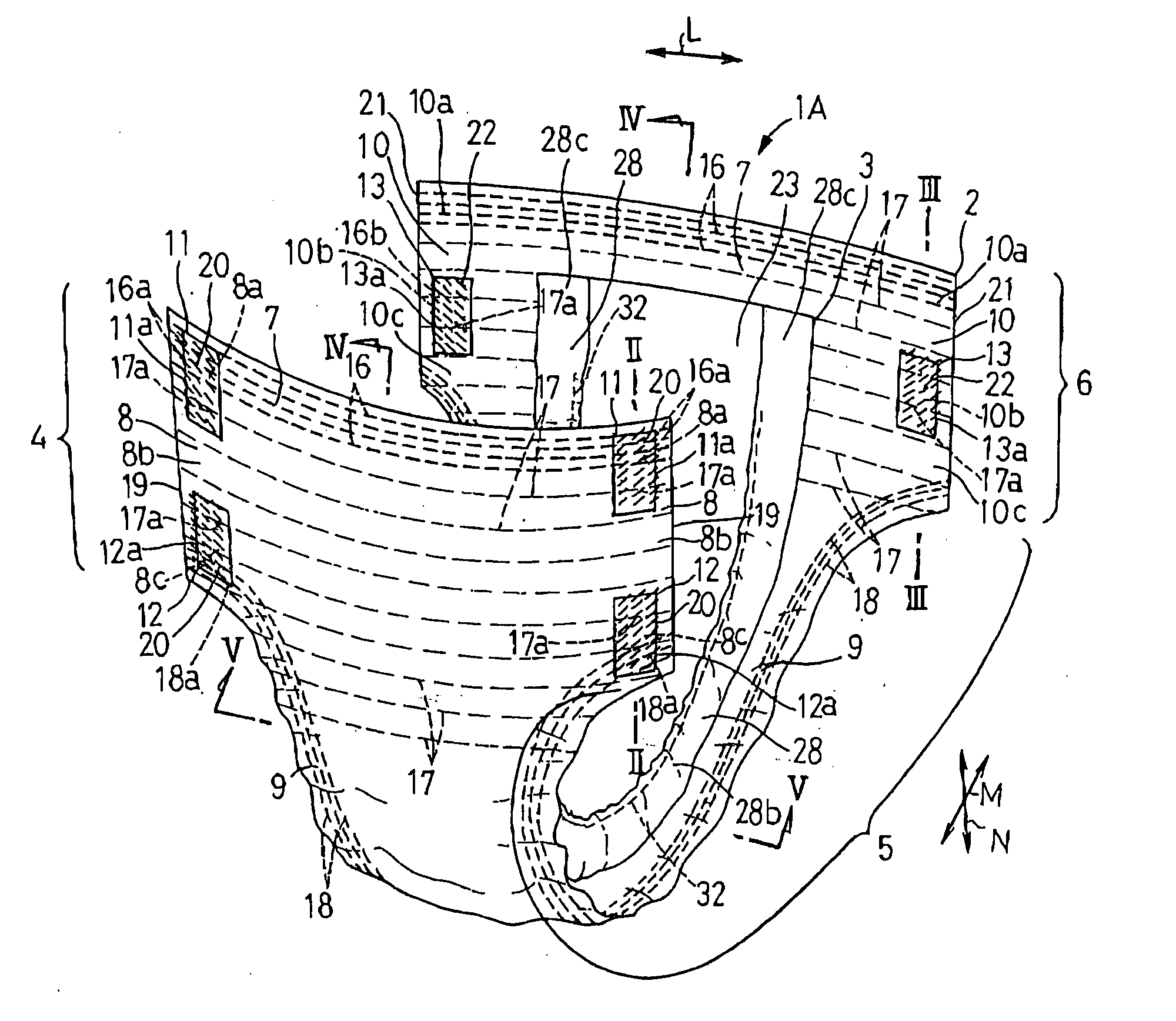
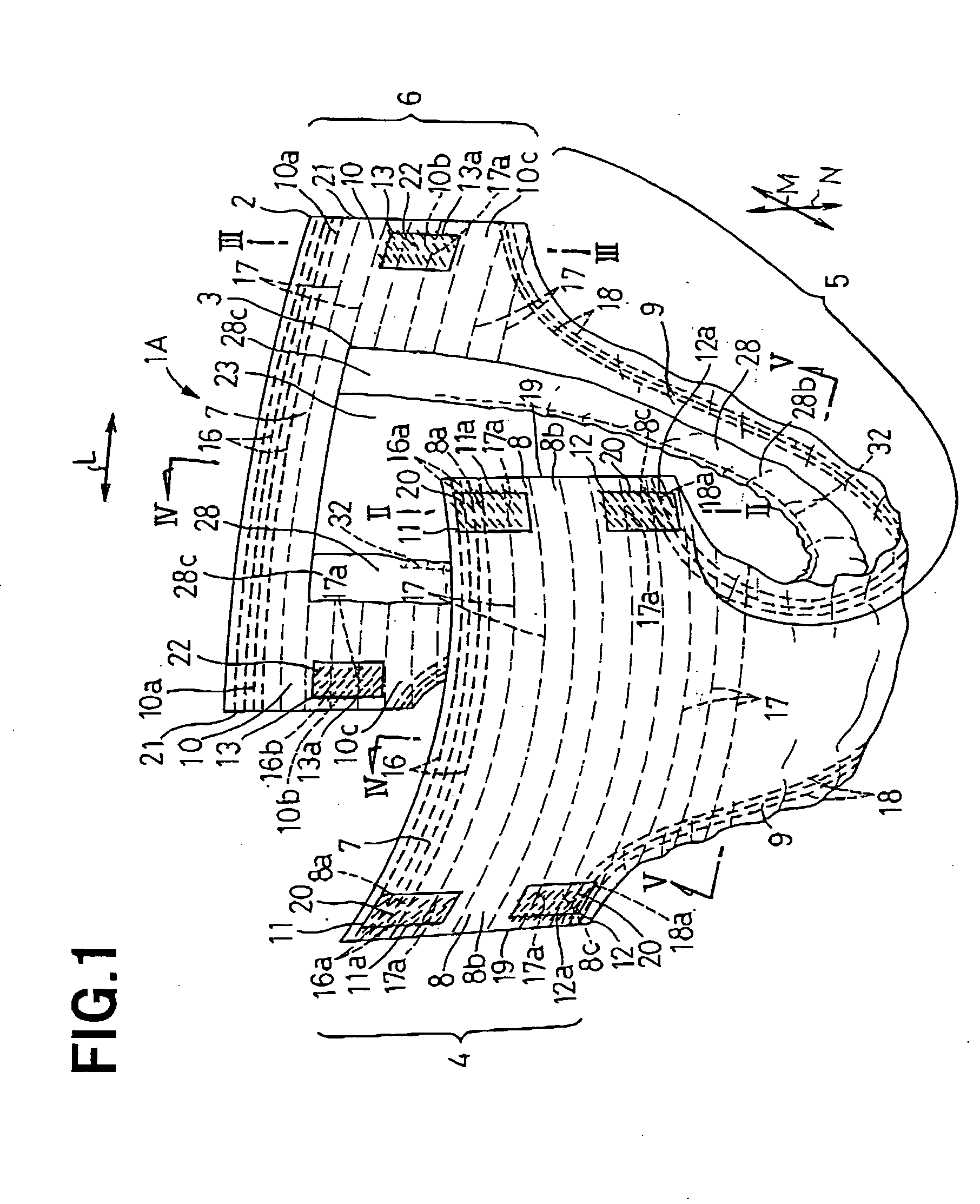
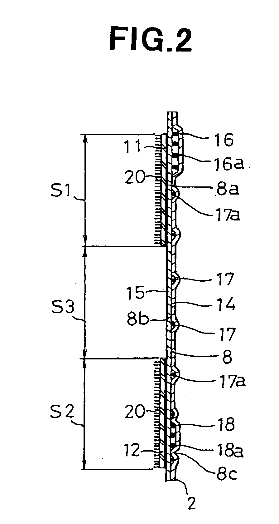
[0036]FIG. 1 is a partially cutaway perspective view showing a disposable wearing article 1A according to a typical embodiment of the invention, FIG. 2 is a sectional view taken along the line II-II in FIG. 1, FIG. 3 is a sectional view taken along the line III-III in FIG. 1 and FIG. 4 is a sectional view taken along the line IV-IV in FIG. 1. In FIG. 1, a transverse direction is indicated by an arrow L, a longitudinal direction is indicated by an arrow M and a thickness direction is indicated by an arrow N. As used herein, the term “inner surfaces” of an outer sheet 2, engagement members 11, 12, 13 and top- and backsheets 23, 24 refers to the surfaces thereof facing the wearer's skin and the term “outer surfaces” thereof refers to the surfaces thereof facing away from the wearer's skin.

[0037...


PUM


Abstract

A disposable wearing article includes first and second engagement members attached to the outer surface of a front waist region along transversely opposite side edge portions thereof so as to be spaced from each other by a given dimension in a longitudinal direction and third engagement members attached to in the inner surface of a rear waist region along transversely opposite side edge portions thereof. The first engagement embers are laid on the respective side edge portions in longitudinally upper zones, the second engagement members are laid on the side edge portions in longitudinally lower zones, the third engagement members are laid on the side edge portions in longitudinally intermediate zones and hooks are respectively formed on the outer surface of the first and second engagement members and on the inner surface of the third engagement members.

Description

BACKGROUND OF THE INVENTION [0001] The present invention relates to a disposable wearing article used to absorb and then to retain bodily waste discharged thereon. [0002] There has already been disclosed a disposable wearing article having front and rear waist regions, a crotch region extending between these two waist regions, and engagement members extending in a longitudinal direction and attached to transversely opposite side edge portions in the front and rear waist regions so that the side edge portions of the front waist region and the side edge portions of the rear waist region may be connected together by means of these engagement members (See Japanese Unexamined Utility Model Application Publication No-1994-55623, herein after referred to as “Citation”). One of the engagement members is defined by hooks constituting the so-called mechanical fastener and attached to the outer surface of the rear waist region along the transversely opposite side edge portions thereof and the ...

Claims


Application Information

Patent Timeline
24 Feb 2005
Publication
US20050043700A1
IPC
A61F13/49; A61F5/44; A61F13/15; A61F13/20; A61F13/494; A61F13/514; A61F13/551; A61F13/56; A61F13/62
CPC
A61F13/5622; A61F13/5633
Inventors
OTSUBO, TOSHIFUMI; SUGITO, TOMOKO