Apparatus for separating liquid from a process gas stream of an electrochemical cell stack

a technology of electrochemical cell and process gas stream, which is applied in the direction of liquid degasification, separation process, auxillary pretreatment, etc., can solve the problems of reducing the efficiency of the electrochemical cell and controlling the removal of water from the process

Active Publication Date: 2005-03-03
HYDROGENICS CORP
View PDF16 Cites 21 Cited by
  • Summary
  • Abstract
  • Description
  • Claims
  • Application Information

AI Technical Summary

Problems solved by technology

A common problem that has to be addressed, for both fuel cell stacks and electrolyzer stacks, is the controlled removal of water from the process gas streams.
The presence of water in the gas streams reduces the efficiency of the electrochemical cell.

Method used


Image

  • Apparatus for separating liquid from a process gas stream of an electrochemical cell stack
  • Apparatus for separating liquid from a process gas stream of an electrochemical cell stack
  • Apparatus for separating liquid from a process gas stream of an electrochemical cell stack

Examples


Embodiment Construction

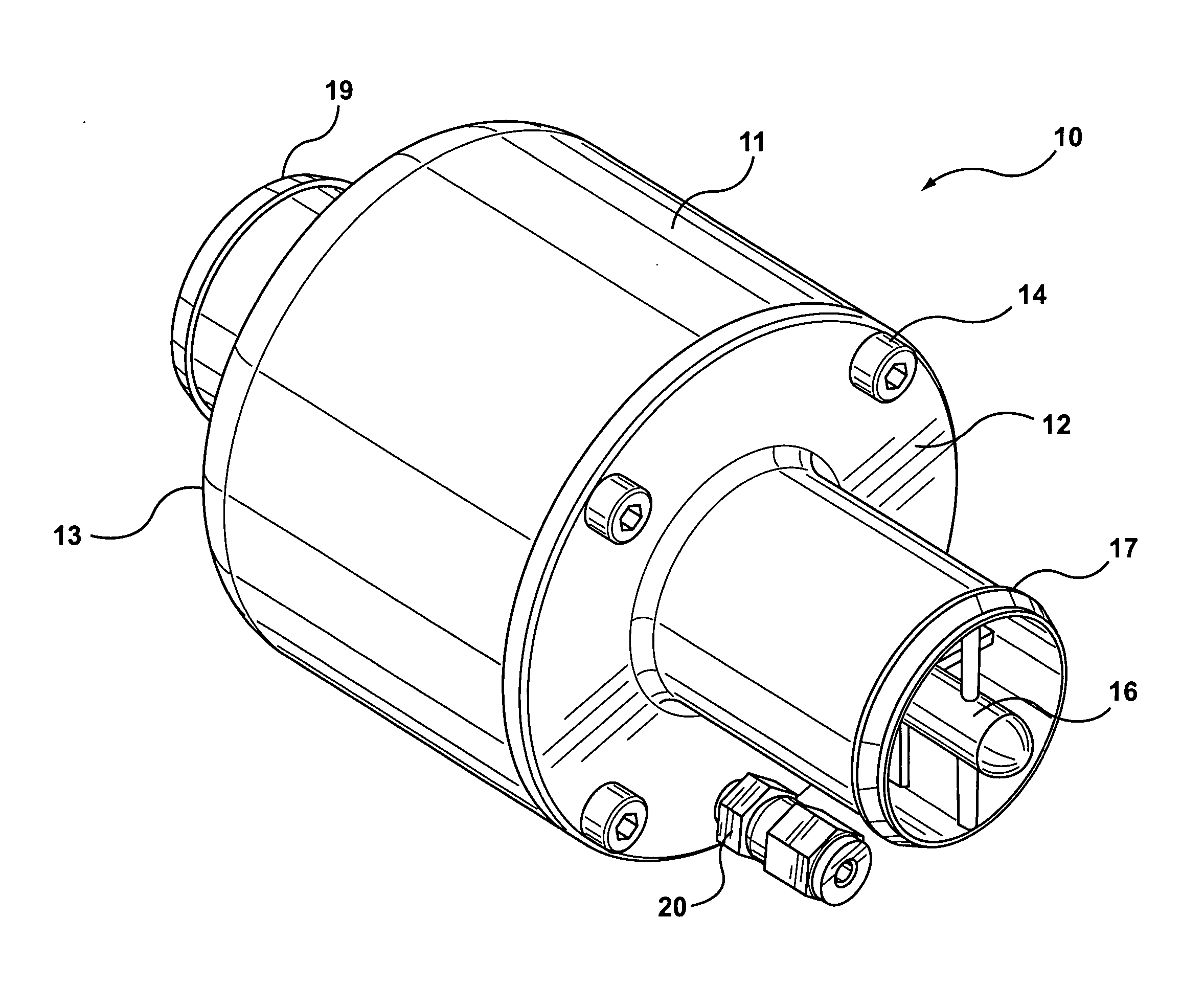
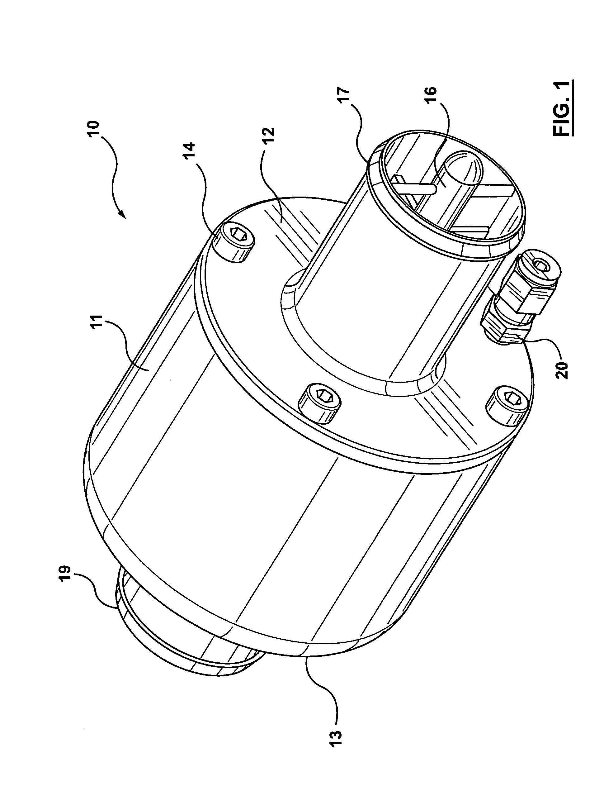
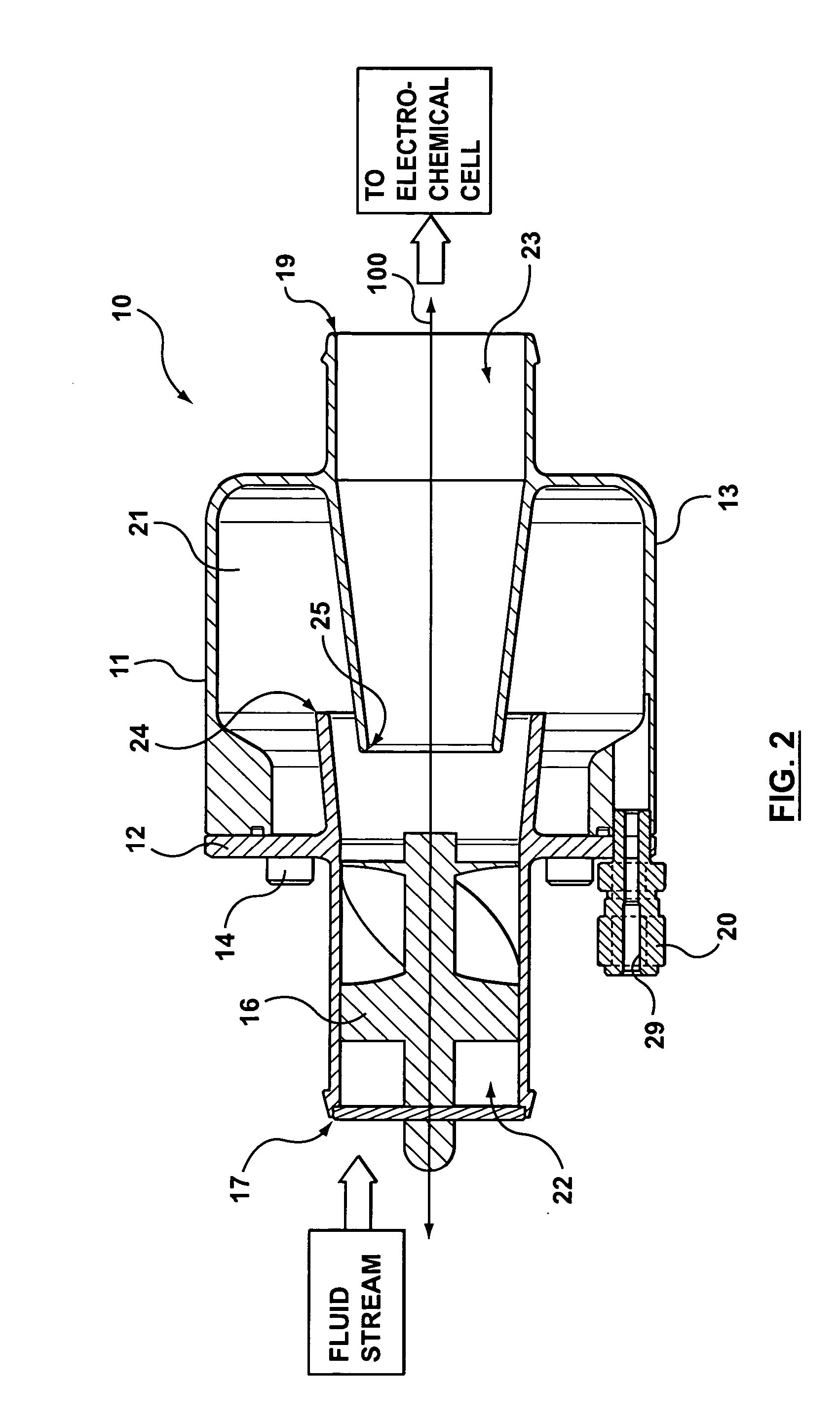
[0019] Referring simultaneously to FIGS. 1 and 2, illustrated therein is a liquid separator, referred to generally as 10, made in accordance with the present invention. The separator 10 includes a main housing 11 having a cap portion 12 and a base 13. The cap 12 is removably mounted to the base 13, typically through the use of screws 14 or nuts and bolts. A substantially cylindrical separation chamber 21 is provided within an interior region of the housing 11. For most low-pressure applications, the housing 11 may be made of plastic or other suitable material.

[0020] A generally cylindrical inlet channel 22 is provided through the cap 12, and configured for communicating a fluid stream (typically comprising water droplets and oxygen or hydrogen as a process gas) from a first inlet end 17 to a second inlet end 24, proximate the separation chamber 21. An o-ring or other type of seal may be provided around the exterior (or interior) circumference of the inlet channel 22, to facilitate ...


PUM

PropertyMeasurementUnit
pressureaaaaaaaaaa
surface tensionaaaaaaaaaa
diameteraaaaaaaaaa

Abstract

A liquid separator configured to separate liquid from a fluid stream. The separator includes a housing, a separation chamber disposed within the housing, a drain, an inlet channel, a swirler disposed within the inlet channel, and an outlet channel. The drain has a drain passageway for draining liquid from the separation chamber. As well, the inlet channel is configured to communicate the fluid stream from a first inlet end to a second inlet end disposed within the housing and proximate the separation chamber. The outlet channel is configured to communicate the fluid stream from a first outlet end positioned proximate the second inlet end, to a second outlet end remote from the separation chamber. Preferably, the drain passageway comprises an inner diameter which is sized such that the interaction between the surface tension of the liquid and the inner passageway causes some liquid to be retained in the drain passageway, the retained liquid forming a low pressure gas seal of the drain passageway. The drain passageway is preferably substantially horizontal. The housing preferably includes a base and a cap which is removably mountable to the base.

Description

[0001] The present application claims priority from U.S. provisional patent application No. 60 / 497,548, which is incorporated herein by reference in its entirety.FIELD OF THE INVENTION [0002] The present invention relates generally to the field of fluid separators, with common but by no means exclusive application to electrochemical cell systems. BACKGROUND OF THE INVENTION [0003] Fuel cells and electrolyzer cells are generally referred to as electrochemical cells. Fuel cells have been proposed as clean, efficient and environmentally friendly power sources that have various applications. A conventional proton exchange membrane (PEM) fuel cell is typically comprised of an anode, a cathode, and a selective electrolytic membrane disposed between the two electrodes. [0004] A fuel cell generates electricity by bringing a fuel gas (typically hydrogen) and an oxidant gas (typically oxygen) respectively to the anode and the cathode. In reaction, a fuel such as hydrogen is oxidized at the an...

Claims


Application Information

Patent Timeline
Patent Type & Authority Applications(United States)
IPC IPC(8): B01D17/038B01D45/14B01D45/16H01M8/04
CPCB01D45/16Y02E60/50H01M8/04164B04C3/06
Inventor BAZZARELLA, RICARDOSIMPSON, TODD A.
Owner HYDROGENICS CORP
Why Eureka
Try Eureka