Motorized lift device

a technology of motorized lifts and lifts, applied in the direction of lifting devices, cabinets, constructions, etc., can solve the problems of inability to achieve uninterrupted and nearly noiseless function, inability to adjust the speed of the motor, so as to minimize the chatter in the drive mechanism, maximize the sliding contact, and minimize the effect of chatter

Inactive Publication Date: 2005-03-03
BOBER WIESLAW
View PDF28 Cites 45 Cited by
  • Summary
  • Abstract
  • Description
  • Claims
  • Application Information

AI Technical Summary

Benefits of technology

[0034] Several advantages are offered by the present invention. The invention eliminates intermittent binding between base and support units by minimizing the distance between the center of mass of the television and contact points between the units. The invention minimizes chatter in the drive mechanism by directly coupling a reversible motor to a drive screw. The invention minimizes chatter between base and support units by maximizing sliding contact between base and support units.
[0035] In the second embodiment, the invention minimizes chatter and the possibility of binding by...

Problems solved by technology

However, designs are inherently less decorative, less stable, and heavier than tube-based televisions.
Pulleys, belts, cables, and gears as described in the related arts are subject to binding and vibrations, therefore movement is both imprecise and noisy.
When applied to the raising and lowering of a low-profile television, the related arts lack the quality of movement required to achi...

Method used


Image

  • Motorized lift device
  • Motorized lift device
  • Motorized lift device

Examples


second embodiment

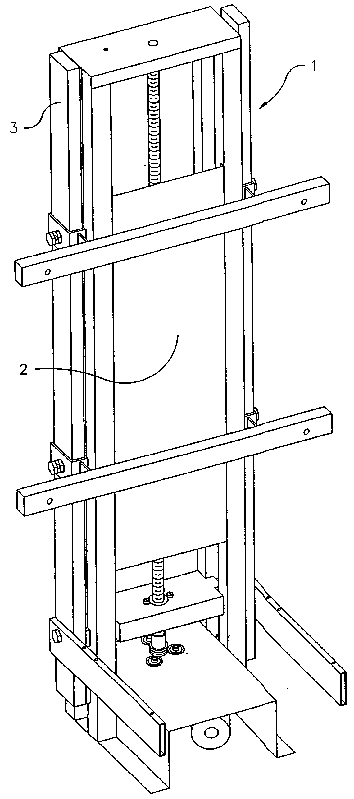
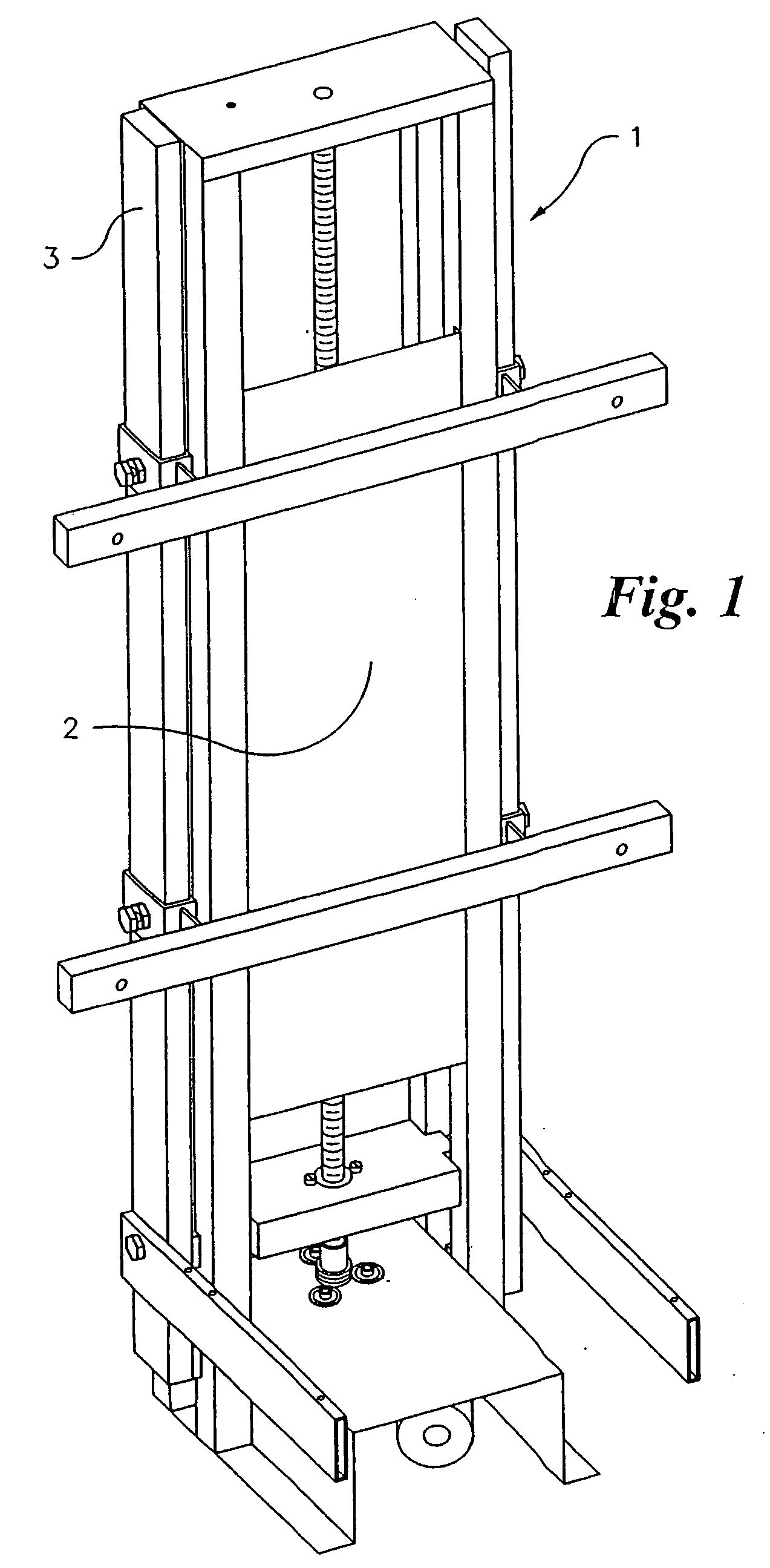
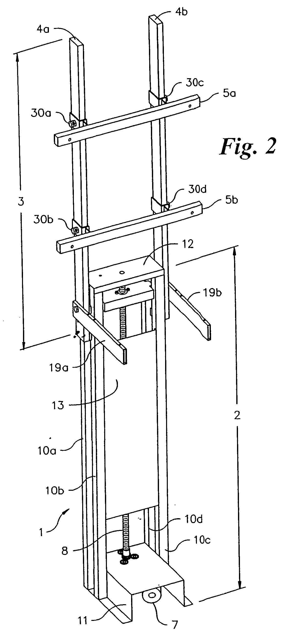
[0080] Referring to FIGS. 11 and 14, the base unit 2 is comprised of the base plate 11, the four rails 10a-10d, the stiffener 13 and an end plate 40 modified to be suitable for the Except for the end plate 40, the base unit has similar features as the embodiment of FIGS. 2-5 which is previously described in detail. Thus, the base plate 11 is an inverted U-shaped element fabricated from sheet metal, preferably steel. Rails 10a-10d are either solid or hollow in construction, preferably having a square or rectangular cross section. Rails 10a-10d are arranged in pairs, 10a-10b and 10c-10d, to either side of the U-shaped base plate 11 so that one end of each rail 10a-10d contacts the base plate 11 adjacent to the lower end 35, as described in FIG. 12. Rails 10a-10d are welded or fastened to the base plate 11, via techniques understood in the art, so as to be upwardly disposed and perpendicular to the base plate 11. Rails 10a-10b and 10c-10d are arranged so as to be physically separated ...

first embodiment

[0095] The motor 104 is located below the base plate 11 and coupled to the transmission 124 via a motor output shaft 138 located at a top of the motor. It is understood that various motors may be used with the motorized lift. For example, a typical reversible and DC powered motor used is manufactured by Valeo Auto-Electric Wischer und Motoren GmbH as previously disclosed in the

[0096] Referring to FIG. 24, the motor output shaft 138 passes through an opening in the base plate 11 and is in direct contact with the transmission 124. The transmission 124, which is cylindrical in shape and hollow, includes a top portion 140, a middle portion 142 and a bottom portion 144, all portions being secured together in a mating relationship. The bottom portion 144 is coupled to the motor output shaft 138 in a mating relationship and may be made of metal. The middle portion 142 is made of a plastic material and also provides insulation from heat dissipating from the power supply and motor. The middl...


PUM


Abstract

A motorized lift device facilitating the uninterrupted and nearly noiseless movement of a low-profile television. The motorized lift comprises a base unit having a support unit slidably disposed thereon in a vertically-oriented and telescoping fashion. Support unit movement is controlled via a motor directly coupled to a transmission which is coupled to a screw. Coupling between screw and an elevator plate converts screw rotation to linear motion within the support unit. A low-friction floating nut between elevator plate and screw, as well as several low-friction couplings between base unit and support unit reduce noise, wobbling, eliminate binding, and accommodates for misalignments during movement. The support unit accommodates for vertical and horizontal adjustability during mounting and installation of any size low-profile television.

Description

CROSS REFERENCE TO RELATED APPLICATIONS [0001] This patent application is a continuation-in-part of U.S. patent application Ser. No. 10 / 361,421, filed on Feb. 10, 2003, and abandoned on Aug. 12, 2004.BACKGROUND OF THE INVENTION [0002] 1. Field of the Invention [0003] The present invention generally relates to a motorized lift. Specifically, the invention is a vertically disposed lift facilitating the uninterrupted and nearly noiseless movement of plasma screen and other low-profile televisions. [0004] 2. Description of the Related Art [0005] Television design trends are focused on low-profile devices including but not limited to plasma screens and LCD panels. Low-profile televisions maximize viewing area and minimize unit depth. However, designs are inherently less decorative, less stable, and heavier than tube-based televisions. [0006] Aesthetic and stability deficiencies of low-profile televisions are addressed by housing the television within a cabinet. In such applications, the ...

Claims


Application Information

Patent Timeline
IPC IPC(8): B66F9/02
CPCB66F9/02A47B81/06A47B9/00B66C23/00B66F9/00
Inventor BOBER, WIESLAW
Owner BOBER WIESLAW
Why Eureka
Try Eureka