Retention system for pivotally connected shutter slats

a technology of pivotal connection and shutter slats, which is applied in the direction of shutter/movable grille, door/window protective devices, construction, etc., can solve the problem that the shutter system cannot move or slide smoothly between the open and closed position with minimal effor

Inactive Publication Date: 2005-03-03
METEOR CREATIVE INC
View PDF28 Cites 8 Cited by
  • Summary
  • Abstract
  • Description
  • Claims
  • Application Information

AI Technical Summary

Benefits of technology

[0004] A pair or set of end caps of rigid molded plastics material are secured to opposite end portions of each slat, and each end cap includes a base portion overlying the end surface of the slat and one or two retention lugs each having a head portion integrally connected to the base portion by a reduced neck portion. The retention lugs project into longitudinally extending undercut chambers formed within elongated vertical side rails which support and guide opposite end portions of the connected slats for movement between an upper retracted position and an extended lower closed position. In the one embodiment, the end caps are secured to the corresponding end portions of a slat by self-tapping screws which extend through the retention lugs and are threaded into the foam core of the slat. In a modified embodiment, each end cap is secured to the corresponding end portion of the slat by a set of bosses which are molded as an integral part of the end cap. The bosses project into the internal chambers of the slat and are bonded by adhesive to the walls of the slat. The end caps also limit relative longitudinal movement between adjacent slats.

Problems solved by technology

If the side rails or retention system are damaged, the shutter system will no longer move or slide smoothly between its open and closed positions with minimal effort.

Method used


Image

  • Retention system for pivotally connected shutter slats
  • Retention system for pivotally connected shutter slats
  • Retention system for pivotally connected shutter slats

Examples


Embodiment Construction

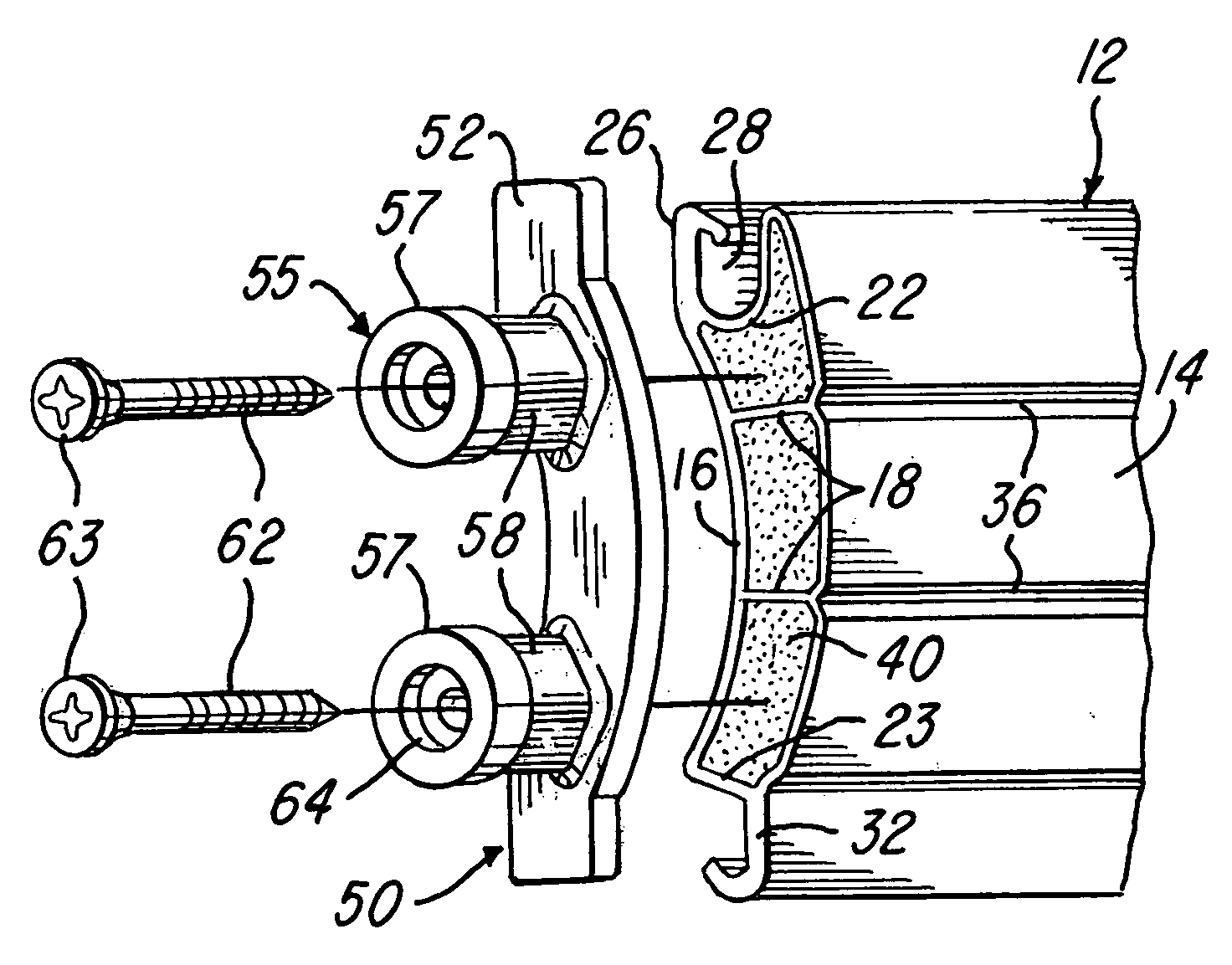
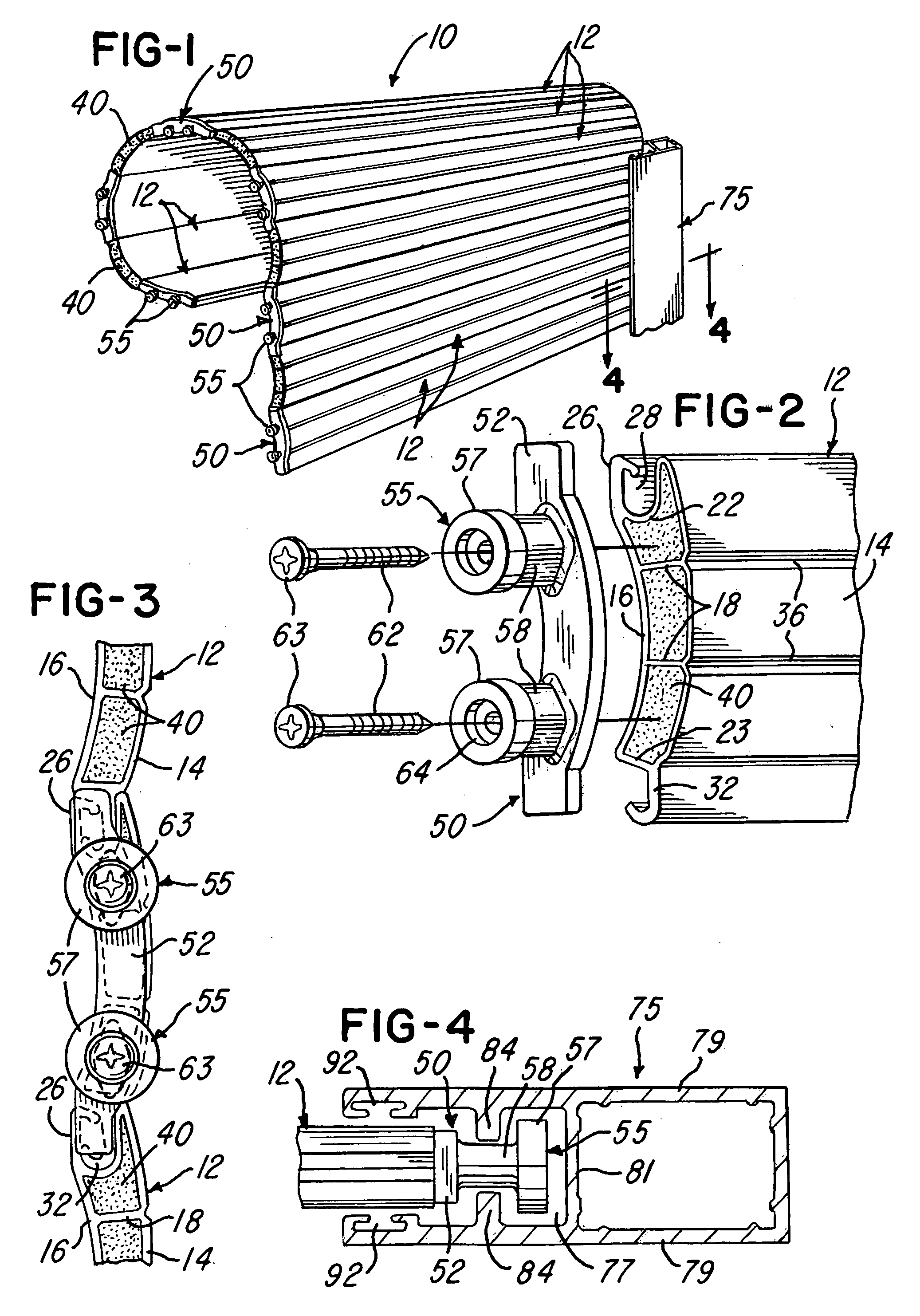
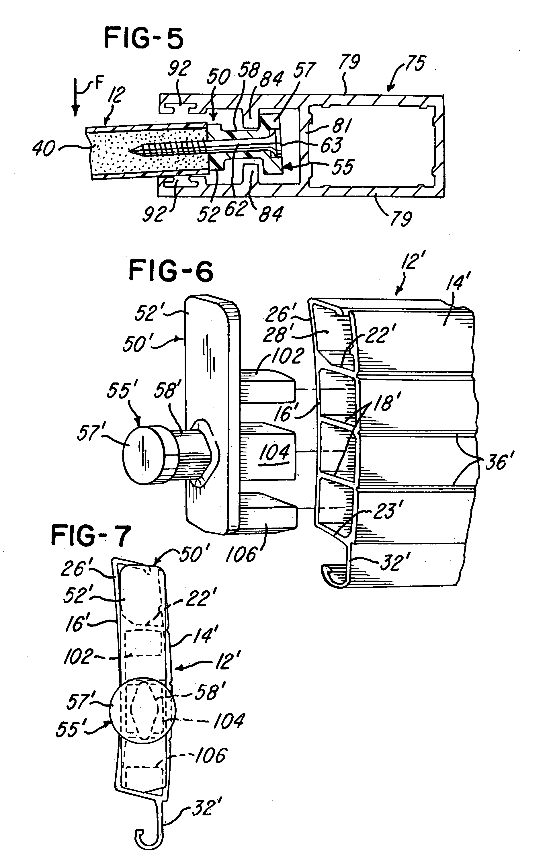
[0013]FIG. 1 illustrates a storm shutter assembly 10 of the roll up type and formed by a plurality of articulated or pivotally connected elongated shutter slats 12 formed from an extrusion of substantially rigid plastics material such as rigid polyvinylchloride (PVC). Each extruded slat 12 includes a slightly arcuate outer side wall 14 and a slightly arcuate inner side wall 16 which are integrally connected by transverse walls including transverse webs or inner walls 18 and transverse longitudinally extending edge walls 22 and 23. An integral hook portion or member 26 projects laterally from the J-shaped edge wall 22 and cooperates with the edge wall 22 to define a longitudinally extending undercut recess 28. Another integral hook portion or member 32 projects from the opposite edge wall 23, and both of the hook portions 26 and 32 have a thickness greater than the thickness of the side walls 14 and 16 and the edge walls 22 and 23.

[0014] The hook portion 32 of each slat 12 is adapte...


PUM


Abstract

A plurality of elongated shutter slats of extruded rigid plastics material have co-extruded cores of rigid plastics foam material, and injection molded plastic end caps are attached to opposite ends of each slat. The end caps have elongated flat base portions and retention lugs with head portions integrally connected to the base portion by reduced neck portions. The lugs of the end caps are retained within undercut channels in extruded metal side rails. In one embodiment, each end cap is secured to a slat by screws extending through two retention lugs and into the foam core. In another embodiment, the end caps are secured to hollow slats by integrally molded bosses which project into cavities within hollow slats and are cemented to the walls of the slat.

Description

BACKGROUND OF THE INVENTION [0001] This invention relates to the retention and support of pivotally connected slats forming a roll-up shutter such as a hurricane or storm shutter and of the general type disclosed in U.S. Pat. No. 5,839,493, the disclosure of which is herein incorporated by reference. The storm shutter slats are commonly made from an aluminum extrusion or an extrusion of rigid plastics material such as rigid polyvinylchloride (PVC), and each slat includes inner and outer arcuate side walls which are integrally connected by longitudinally extending internal webs and longitudinally extending edge walls. The opposite edge walls of each slat commonly form a longitudinally extending hook portion and an undercut cavity or recess which form pivotal connections between adjacent slats so that the connected slats may be rolled up into a coil as shown in the above '493 patent. Other forms of shutter slats and retention systems are disclosed in U.S. Pat. Nos. 5,253,694, 5,996,66...

Claims


Application Information

Patent Timeline
Patent Type & Authority Applications(United States)
IPC IPC(8): E06B9/58
CPCE06B2009/1583E06B9/581
Inventor SCHLATER, TIMOTHY J.WENRICK, BRIAN A.WENRICK, JASON D.YOUNG, JACK D.
Owner METEOR CREATIVE INC
Why Eureka
Try Eureka