Lost motion mechanism for movable vehicle implements

a technology of movable vehicle implements and motion mechanisms, which is applied in snow cleaning, way cleaning, construction, etc., can solve the problems of blade down force, plow constructions that do not include the ability to change blades, and premature wear of winch cables

Inactive Publication Date: 2009-07-28
PARKER HANNIFIN CORP
View PDF34 Cites 8 Cited by
  • Summary
  • Abstract
  • Description
  • Claims
  • Application Information

AI Technical Summary

Benefits of technology

[0006]In order to overcome the deficiencies of the prior art devices, a lost motion mechanism is provided. The lost motion mechanism is operatively interconnected with a hydraulic cylinder. The hydraulic cylinder is rotatably connected to one of a vehicle and an implement. The lost motion mechanism is rotatably connected to the other of the vehicle and the implement. The cylinder and lost motion mechanism cooperate for moving the implement relative to a ground level. The lost motion mechanism comprises in combination: an elongated rod connected with a portion of the hydraulic cylinder; an elongated sleeve member adapted to receive at least a portion of the rod extension, the sleeve member including at least one slot of a predetermined length; and at least one pin member attached relative to the rod extension and protruding into the at least one slot. The pin member together with the slot, limiting the longitudinal movement of the rod extension and enabling the implement to be moved by hydraulic force both upward and downward relative to the ground level as well as enabling the implement to be free floating relative to the ground level.

Problems solved by technology

As a result of the chafing, the winch cable may wear prematurely, and, thus, necessitating frequent replacement, particularly when used in commercial and municipal markets.
In addition, these plow constructions also do not include the ability to change the blade angle unless the operator physically gets off the vehicle in order to manually change same.
These constructions only have the ability to exert a down force on the blade and include no mechanisms that would permit the blade to “float” during operation.
While some further plow constructions use hydraulic power unit systems, these constructions are not designed to withstand an impact if the operator impinges on an object with the plow blade.

Method used


Image

  • Lost motion mechanism for movable vehicle implements
  • Lost motion mechanism for movable vehicle implements
  • Lost motion mechanism for movable vehicle implements

Examples


Embodiment Construction

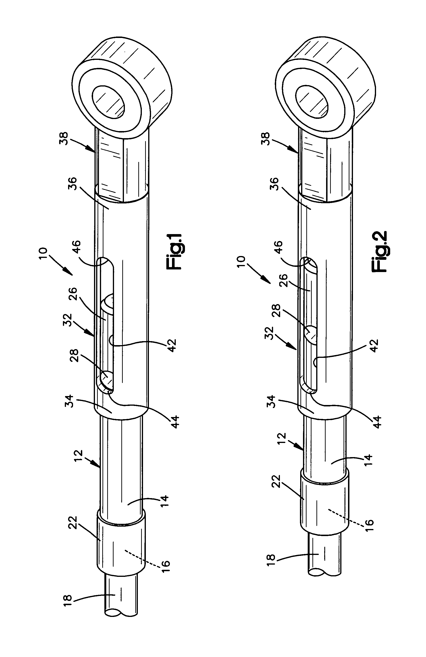
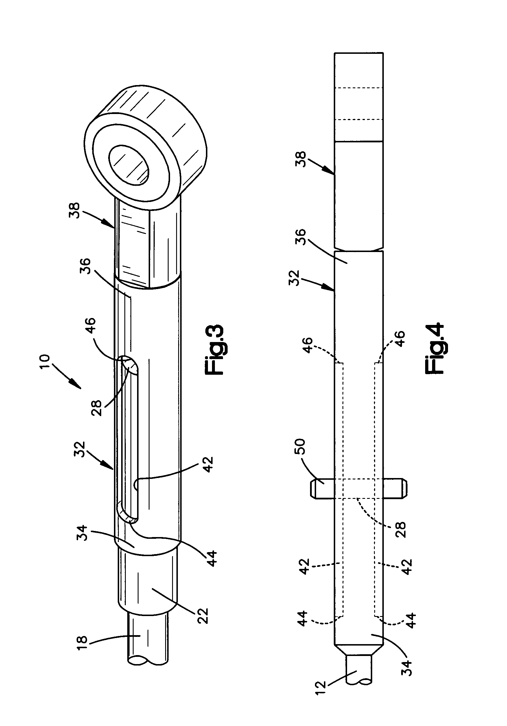
[0027]Referring now to the several drawings, illustrated in FIGS. 1-3 are similar perspective views of the lost motion device (LMD) or mechanism 10 of this invention, but showing same in three differing positions. FIG. 1 shows lost motion mechanism 10 in a fully extended position A, while FIG. 2 shows LMD 10 in an intermediate, floating, position B, with FIG. 3 showing LMD 10 in a fully retracted position C.

[0028]Turning first to FIG. 1 and fully extended position A, LMD 10 includes an elongated rod extension 12 affixed on an inner end 14 thereof, to the outer end 16 of the piston rod or output member 18 of a double-acting hydraulic cylinder 20 (FIGS. 5-11). This affixation may, for example, take the form of an internally-threaded, increased diameter, rod inner end portion of piston rod outer end 16. Rod extension 12 also includes at a predetermined distance from an outer end 26 thereof, a lateral bore or through hole 28, perpendicular to the axial extent of rod extension 12.

[0029]A...


PUM


Abstract

A lost motion mechanism that is operatively interconnected with a hydraulic cylinder is provided. The lost motion mechanism includes an elongated rod connected with a portion of the hydraulic cylinder. An elongated sleeve member is adapted to receive at least a portion of the rod extension. The sleeve member includes at least one slot of a predetermined length. At least one pin member is attached relative to the rod extension and protrudes into the at least one slot. The pin member together with the slot limits the longitudinal movement of the rod extension and enables an implement to be moved by hydraulic force both upward and downward relative to ground level as well as enables the implement to be free floating relative to the ground level.

Description

CROSS REFERENCE TO RELATED APPLICATIONS[0001]The present application claims the benefit of the filing date of U.S. Provisional Patent Application Ser. No. 60 / 778,684, filed Mar. 3, 2006, the disclosure of which is incorporated herein by reference.FIELD OF THE INVENTION[0002]The present invention pertains to an apparatus for moving, relative to ground level, of a mounted implement on a vehicle. More particularly, the invention pertains to the operative interpositioning of a lost motion mechanism between a piston rod output end and either the vehicle or the implement, thereby permitting full lowering the implement to the ground level in a floating condition without fluid-power forces acting thereon.BACKGROUND OF THE INVENTION[0003]Most of the current plow constructions used on vehicles, such as, e.g. ATV (All-Terrain Vehicles) utilize one of two different structures and methods for actuating the scraper blades on snowplow systems. The first structure and method of operation utilizes a...

Claims


Application Information

Patent Timeline
Patent Type & Authority Patents(United States)
IPC IPC(8): E01H5/04
CPCE01H5/06
Inventor ALMADANI, MAZEN W.
Owner PARKER HANNIFIN CORP
Why Eureka
Try Eureka