
Pulling tool

a technology of pulling tool and pulling rod, which is applied in the direction of drilling pipe, drilling casing, and accessories of wells, etc., can solve the problems of not being able to pull the tool or plug out of the well, not being able to operate the tool, and damage to the tool, etc., and achieve the effect of reliable disengagement system

Active Publication Date: 2014-10-23
WELLTEC AS
View PDF6 Cites 9 Cited by
  • Summary
  • Abstract
  • Description
  • Claims
  • Application Information

AI Technical Summary

Benefits of technology

The present invention relates to an improved pulling tool and retrieval system with a reliable disengagement system. The pulling tool comprises a base element with a protruding flange for securely latching onto an object in a wellbore and preventing excessive radial movement. The base element also has a protrusion restricting longitudinal movement of the key element beyond the protrusion. The piston spring force prevents the latching mechanism from being activated when hydraulic pressure is lost. The use of a common hydraulic system and mounting of the pulling tool on the piston rod reduces the total length of the retrieval system, which is often limited by the BOP.

Problems solved by technology

However, in some cases the anchoring mechanism may get stuck, or it might not be possible to pull the tool or plug out of the well for other reasons.
One of the disadvantages of the known pulling tools is that the tools are damaged or become inoperable following the activation of the fail-safe mechanism.

Method used


Image

  • Pulling tool
  • Pulling tool
  • Pulling tool

Examples


Embodiment Construction

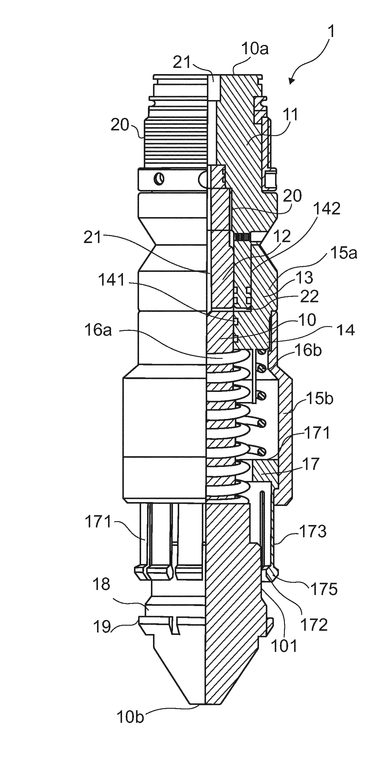
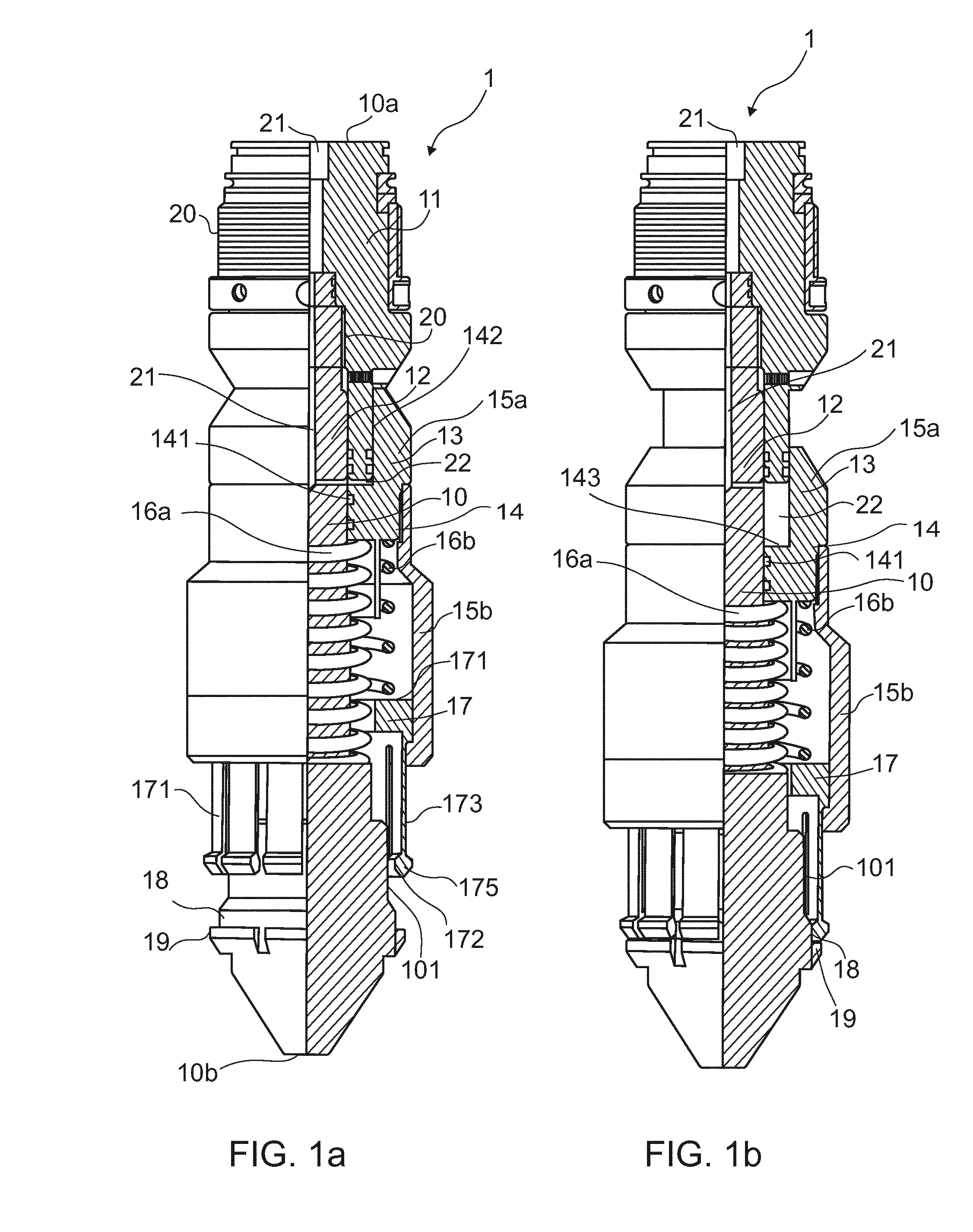
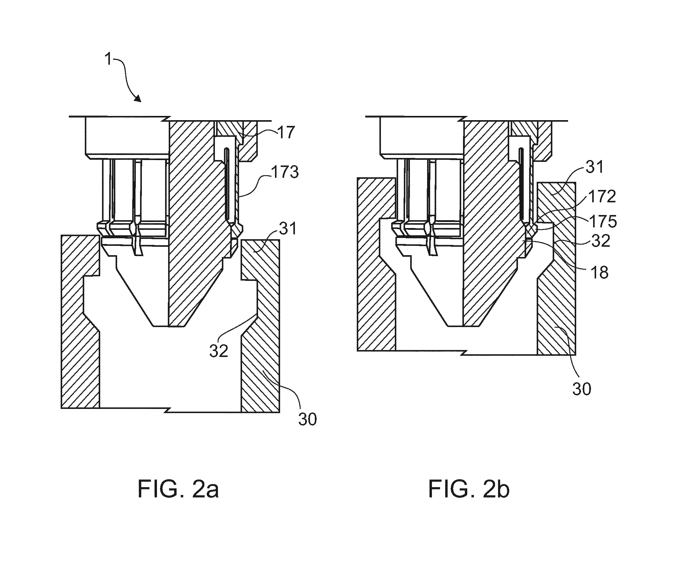
[0060]FIGS. 1a and 1b show a pulling tool 1 in a deactivated state and an activated state, respectively. The pulling tool 1 comprises a base element 10 extending in a longitudinal direction from a proximal end 10a for being connected to a wireline tool, to a distal end 10b adapted to engage a downhole object. The proximal end of the pulling tool 1 may alternatively be connected to a coiled tubing tool, coiled tubing or a drill string for insertion in the well. The pulling tool 1 further comprises a latching mechanism 13 encircling the base element 10 and being movable in the longitudinal direction between a deactivated position as shown in FIG. 1a and an activated position as shown in FIG. 1b.

[0061]The latching mechanism 13 comprises a piston sleeve 14 slidably received around the base element 10. The piston sleeve 14 thus constitutes an exterior annular piston movable in the longitudinal direction along the base element 10. The latching mechanism further comprises a key element 17...


PUM


Abstract

The present invention relates to a pulling tool (1) for latching onto an object (30), such as a plug, downhole in a wellbore The pulling tool comprises a base element (10) extending in a longitudinal direction from a proximal end (10a) for being connected to a wireline tool to a distal end (10b) adapted to engage the object, and a latching mechanism (13) encircling the base element and being movable in the longitudinal direction between a deactivated position and an activated position, comprising a piston sleeve (13), a key element (17) for latching onto the downhole object, the key element being slidably received inside the piston sleeve and extending from an end of the piston sleeve towards the distal end of the base element, and a piston spring forcing (16a) the piston sleeve in the longitudinal direction towards the proximal end of the base element. Furthermore, the present invention relates to a downhole retrieval system for pulling an object in a well-bore and to a method of connecting and disconnecting such retrieval system to a downhole object.

Description

FIELD OF THE INVENTION[0001]The present invention relates to a pulling tool for latching onto an object, such as a plug, downhole in a wellbore. Furthermore, the present invention relates to a downhole retrieval system for pulling an object in a wellbore and to a method of connecting and disconnecting such retrieval system to a downhole object.BACKGROUND ART[0002]Known downhole pulling tools are often fully mechanical tools, wherein a mechanical locking mechanism is used to provide a rigid connection between the pulling tool and an object to be retrieved downhole, such as downhole plugs, tools, etc. The mechanical locking mechanism often comprises locking means, such as keys, dogs or fingers, extending from the body of the pulling tool to engage a recess, also denoted as a fishing neck, in the object to be retrieved. The locking means are usually locked in the fishing neck by applying a pulling force to the pulling tool, and subsequently the object may be pulled out of the well.[000...

Claims


Application Information

Patent Timeline
Patent Type & Authority Applications(United States)
IPC IPC(8): E21B23/04E21B31/12
CPCE21B31/12E21B23/04E21B31/20E21B23/042E21B17/06E21B31/18
Inventor HALLUNDB.AE BUTTED.K, JORGENEVERTSEN, STEFFENSOMMER, RASMUS
Owner WELLTEC AS
Learn More