This helps you quickly interpret patents by identifying the three key elements:
Problems solved by technology
Method used
Benefits of technology
Benefits of technology
[0010] It is an object of the present invention to provide a panel cutting machine of straightforward design, and which provides for faster performance of cutting schemes comparable in complexity to that of the machine briefly described above.
Problems solved by technology
Though undoubtedly an improvement as compared with existing machines, the cutting machine described is extremely expensive and difficult to maintain, on account of each gripper being operated by respective actuators, which are therefore complicated to control.
Moreover, for certain cutting schemes, the machine described is fairly limited.
Method used
Image
Click on the blue label to locate the original text in one second.
Reading with bidirectional positioning of images and text.
Examples
first embodiment
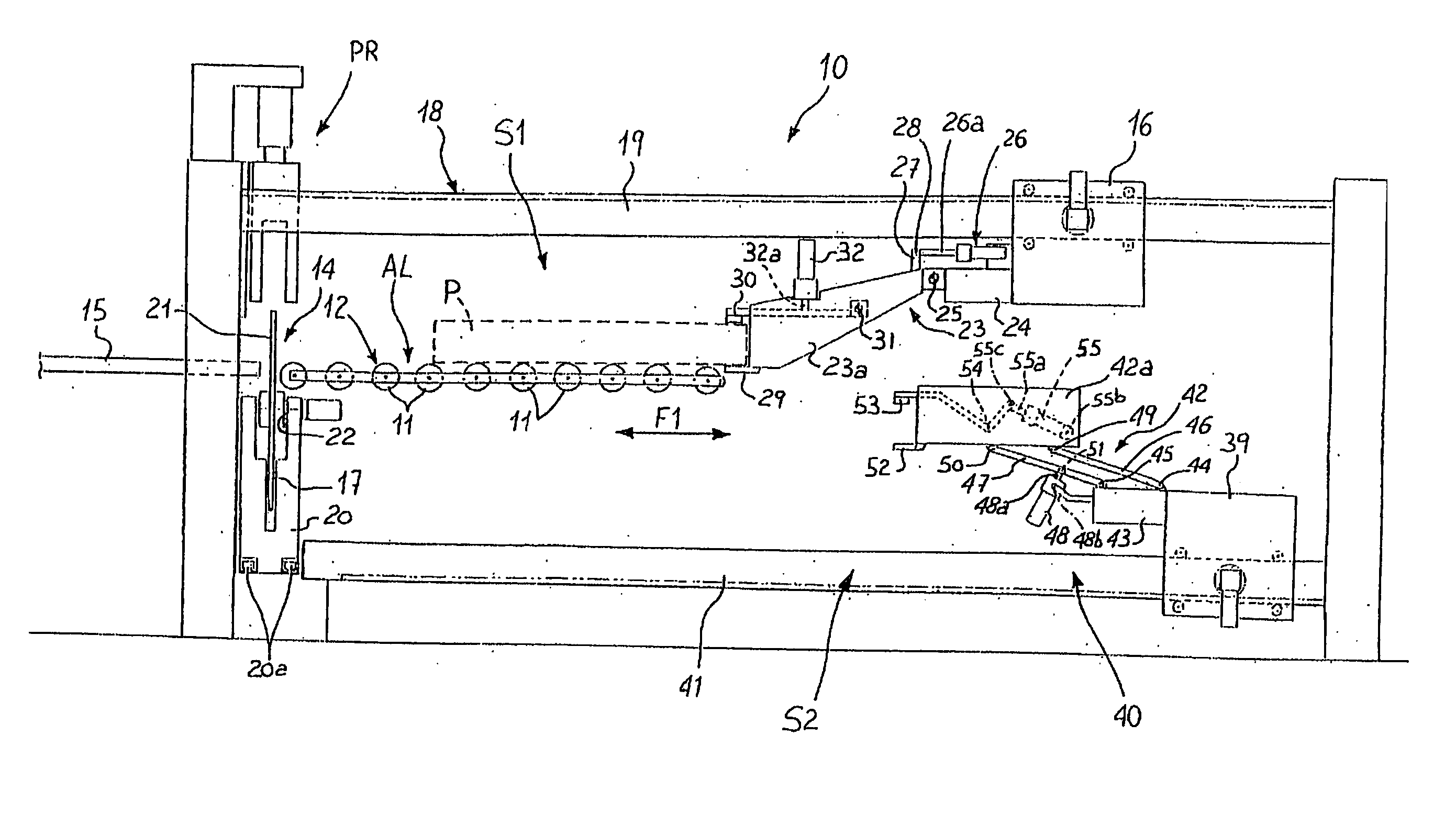
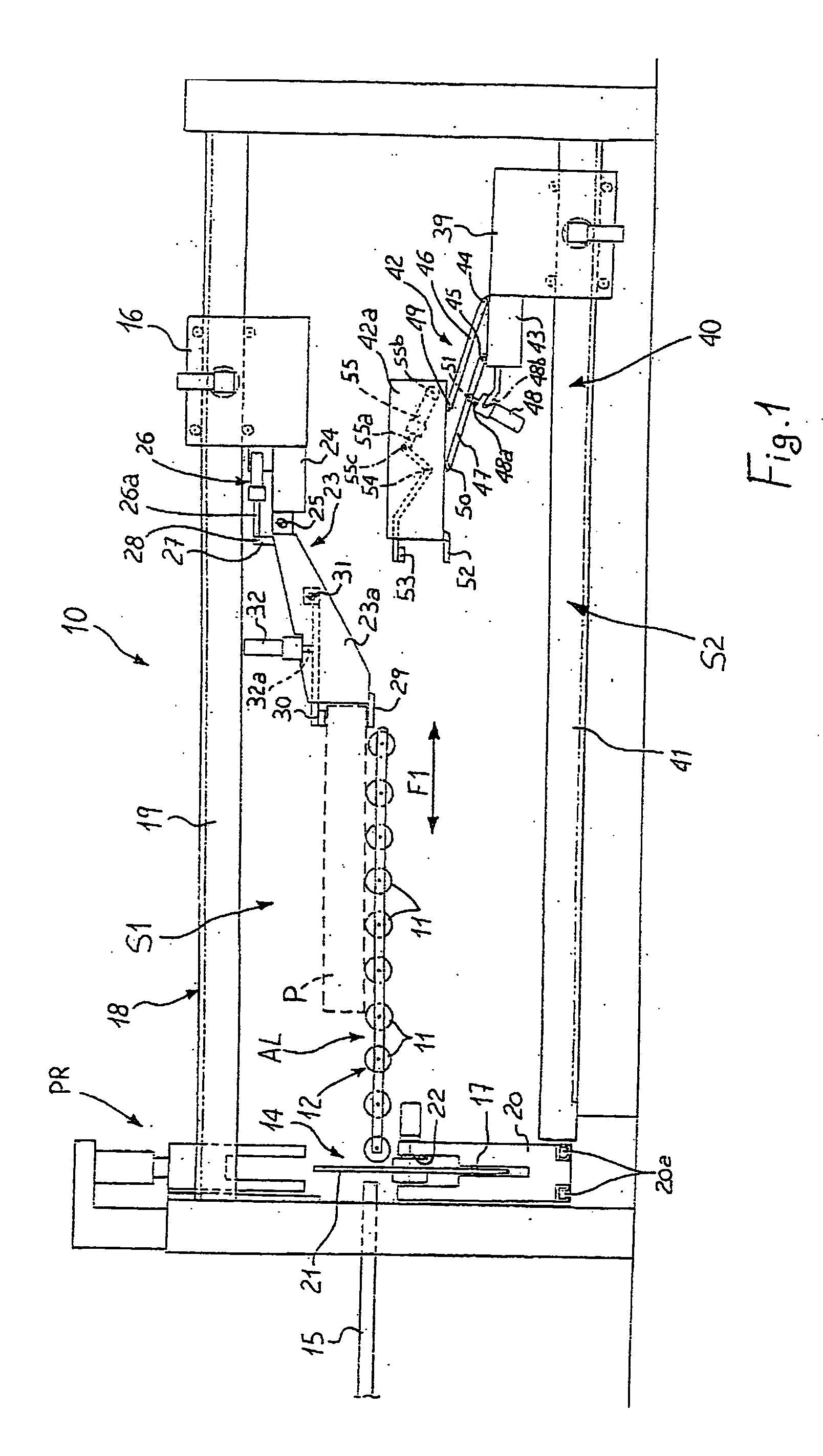
[0020] Number 10 in FIG. 1 indicates as a whole a cutting machine for cutting panels P used to manufacture products (not shown).
[0021] Cutting machine 10 comprises a first system S1 for handling panels P.
[0022] More specifically, first system S1 extends along an axis A1 (FIG. 3), and comprises a set of supporting rollers 11 forming a horizontal table 12 for supporting panels P.
[0023] Table 12 defines a work area AL of first system S1.
[0024] Table 12 ideally continues in known manner in the form of a number of supporting surfaces 15 beyond a cutting section 14 described in detail later on.
[0025] Panels P are held firmly during the cutting operation by a pressure device PR located in known manner at cutting section 14. For the sake of simplicity, pressure device PR is only shown in FIGS. 1,2 and 4.
[0026] An operator (not shown) can therefore move in known manner between supporting surfaces 15 to turn and position panels P manually as required with respect to cutting section 14.
[...
second embodiment
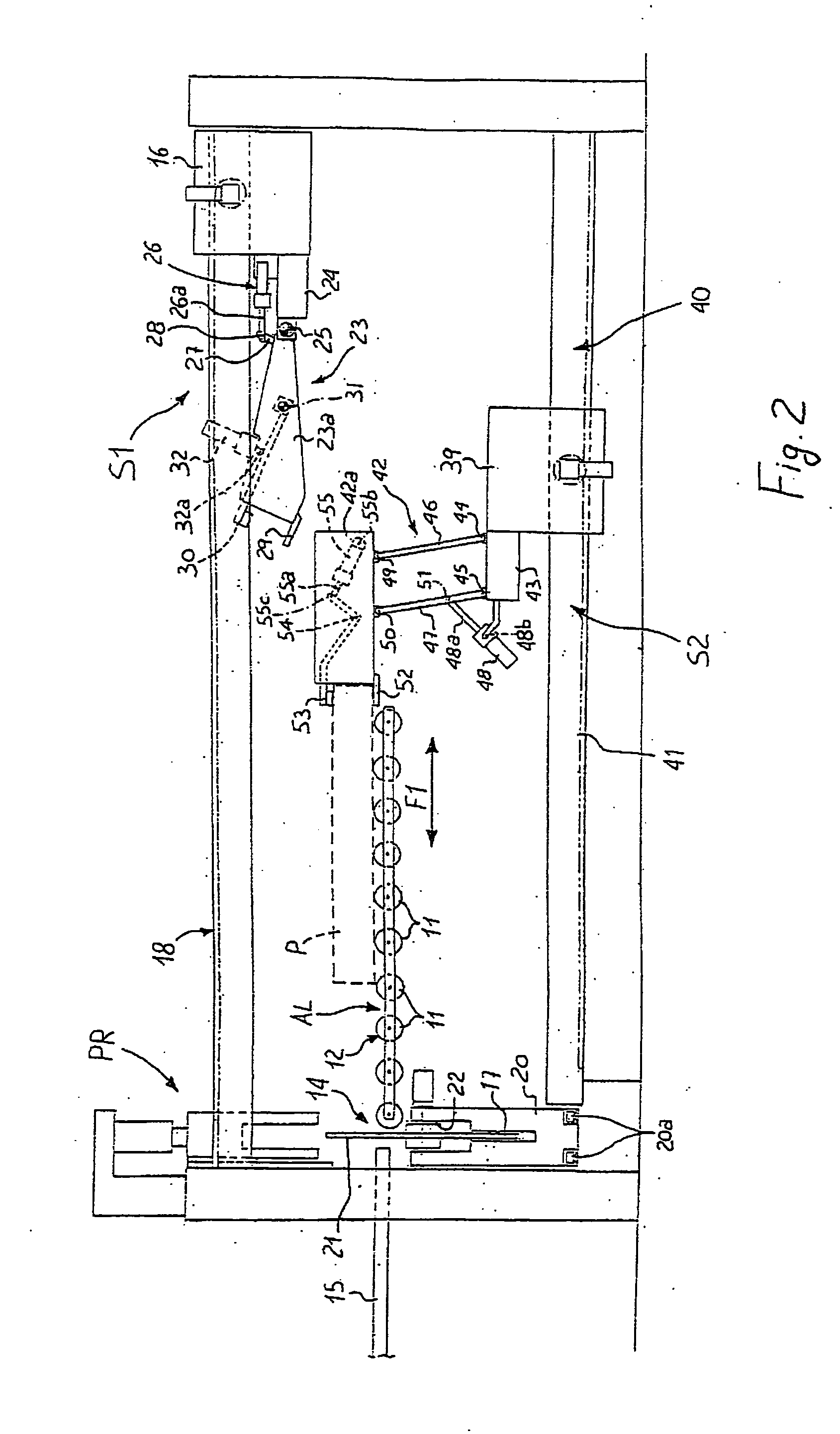
[0075] In the second embodiment shown in FIGS. 4 to 7, first system S1 for handling panels P is practically the same, whereas the component parts of second system S2 differ.
[0076] First system S1 is therefore not described as a whole, and, where necessary, reference is made to the description given of it in the first embodiment with reference to FIGS. 1 to 3.
[0077] Unlike the first embodiment in FIGS. 1 to 3, however, the second embodiment in FIGS. 4 to 7 comprises a drive 56 for driving carriage 16 of first system S1.
[0078] As shown in FIGS. 5 and 6, carriage 16 rests on two top longitudinal members 19A, 19B of guide 18, and in particular on two “dovetail” guide members 57, along which it is slid freely by two electric motors 58, 59, each having a respective toothed pinion 58a, 59a meshing with a respective rack 60, 61 fixed to respective longitudinal member 19A, 19B.
[0079] Rotation of toothed pinions 58a, 59a, controlled by the electronic central control unit (not shown), moves...
PUM
Property
Measurement
Unit
Time
aaaaa
aaaaa
Area
aaaaa
aaaaa
Abstract
A cuttingmachine for cutting panels has two separate systems for handling the packs of panels, and defines a work area common to both systems.
Description
[0001] The present invention relates to a panel cuttingmachine. [0002] More specifically, the present invention relates to a machine for cutting panels used in the manufacture of furniture, to which the following description refers purely by way of example. BACKGROUND OF THE INVENTION [0003] A machine for cutting furniture panels normally comprises a horizontal table supporting the panels; a push or gripper carriage for moving the panels along the table in a first direction parallel to the table; and a panel cutting tool movable in a second direction perpendicular to the first direction. [0004] The push or gripper carriage and the cutting tool are guided respectively by a first guide and a second guide perpendicular to the first guide. [0005] The push carriage normally runs along a first guide comprising two rails, which extend over the table, are parallel to the first direction, and support opposite ends of the carriage. [0006] In known embodiments, the carriage comprises wheels, ...
Claims
Application Information
Patent Timeline
Application Date:The date an application was filed.
Publication Date:The date a patent or application was officially published.
First Publication Date:The earliest publication date of a patent with the same application number.
Issue Date:Publication date of the patent grant document.
PCT Entry Date:The Entry date of PCT National Phase.
Estimated Expiry Date:The statutory expiry date of a patent right according to the Patent Law, and it is the longest term of protection that the patent right can achieve without the termination of the patent right due to other reasons(Term extension factor has been taken into account ).
Invalid Date:Actual expiry date is based on effective date or publication date of legal transaction data of invalid patent.

