Coupler for flexible hose sections

Inactive Publication Date: 2005-03-03
ABC MFR OF CANADA
2 Cites 8 Cited by

AI-Extracted Technical Summary

Problems solved by technology

The couplers for connecting the hose sections are typically zippers or zippers combined with hook and loop, in both cases these zipper style couplers are difficult to connect, and subject to breakage.
Actually making this coupling is problematic, since the elements on each section grab each other when the male end is inserted, resisting moving the elements into a proper relationship with respect to each other.
As the adjacent ends are not inserted in a ...

Method used

[0029] The female portion 4 has a flat width FW when laid flat as in FIG. 2, and for ease of coupling the slit 12 has a length SL such that the slit end 16 is located a distance that is more than one half of the flat width FW from the end edge 14 of the female portion 4. A shorter slit will offer some improvement in ease of coupling, however it is contemplated that a slit length SL of one half to three quarters of the flat width FW will be generally used in practice.
[0030] Thus in the embodiment of FIGS. 1-4 the first and second elements 8, 9 of the hook and loop coupling fastener 10 are in a narrow band at the end of the female portion 4. The slit 12 extends considerably farther along the female portion 4 than the hook and loop coupling fastener 10 such that when the female portion 4 is spread open along the slit, it is relatively easy to insert the male portion 6 to a midpoint of the slit 12 where the end edge thereof is between the coupling terminus 15 and the slit end 16. The great majority of the second element 8 is exposed when the female portion 4 is spread open along the slit 12 as illustrated in FIG. 2, such that only a minor amount of tucking is required to properly position the male portion 6 inside the opened female portion 4.
[0032] To prevent air leakage in the embodiment of FIGS. 1-4, a flap 20 is attached to the outside surface of the female portion 4 along a first side of the slit 12. A first element 21 of a hook and loop flap fastener 23 is attached to an inner face 25 of the flap 20, and a second element 22 of the hook and loop flap fastener 23 is attached to the outside surface of the female portion 4 along an opposite second side of the slit 12.
[0033] The flap 20 is oriented such that the first element 21 of the hook and loop flap fastener 23 on the inner face 25 of the flap 20 can be pressed against the second element 22 of the hook and loop flap fastener 23 to cover the slit 12, as illustrated in FIG. 4. The illustrated flap 20 can be incorporated into any of the other illustrated embodiments as well where further security of sealing is desired. The illustrated flap 20 and the second element 22 of the hook and loop coupling fastener 23 extend from the end edge 14 of the female portion 4 beyond the slit end. By extending the flap 20 and hook and loop flap fastener 23 beyond the slit end 16, better sealing is provided. In prior art couplings with two slits, the flap 20 ends at the slit end 16, and the end edge 18 of the male portion 6 is also located at the slit end 16. Air leakage occurs at this point through the end of each of the pair of slits in the prior art since there is essentially a hole at this point where the flap, slit, and male portion meet.
[0034] By reducing the number of slits to one in the present inven...

Benefits of technology

[0010] It is an object of the present invention to provide an air hose made up from hose sections using a coupling that overcomes problems in the prior art. It is a...

Abstract

A flexible air hose comprises a plurality of hose sections, each having at one end a female portion and at an opposite end a male portion coupled inside the female portion of an adjacent hose section. A loop coupling fastener is attached to an inside surface of the female portion, and a corresponding area of an outside surface of the male portion. A single slit extends from an end edge of the female portion of the hose section longitudinally along the hose section such that the female portion can be opened along the slit to facilitate positioning the male portion inside the female portion. A flap can be provided to cover the slit, and extend past the slit end to reduce air leakage. A wear strip can be wrapped around the hose.

Application Domain

Ducting arrangementsLighting and heating apparatus +1

Technology Topic

FastenerEngineering +2

Image

  • Coupler for flexible hose sections
  • Coupler for flexible hose sections
  • Coupler for flexible hose sections

Examples

  • Experimental program(1)

Example

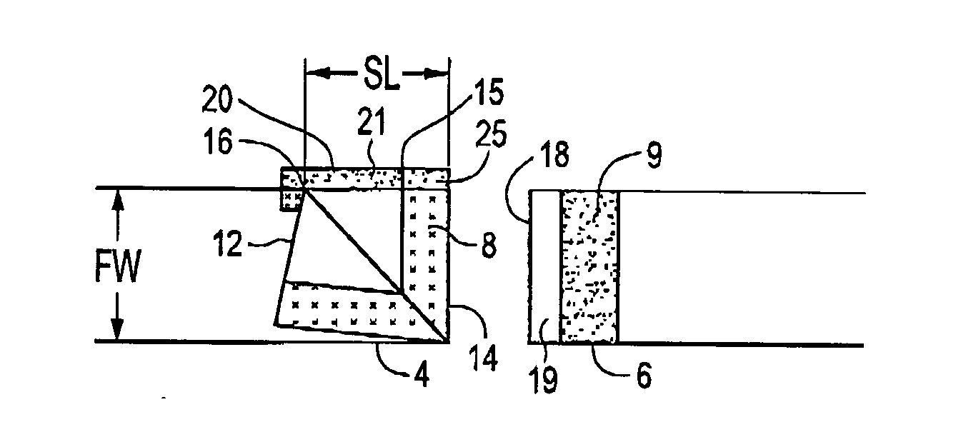
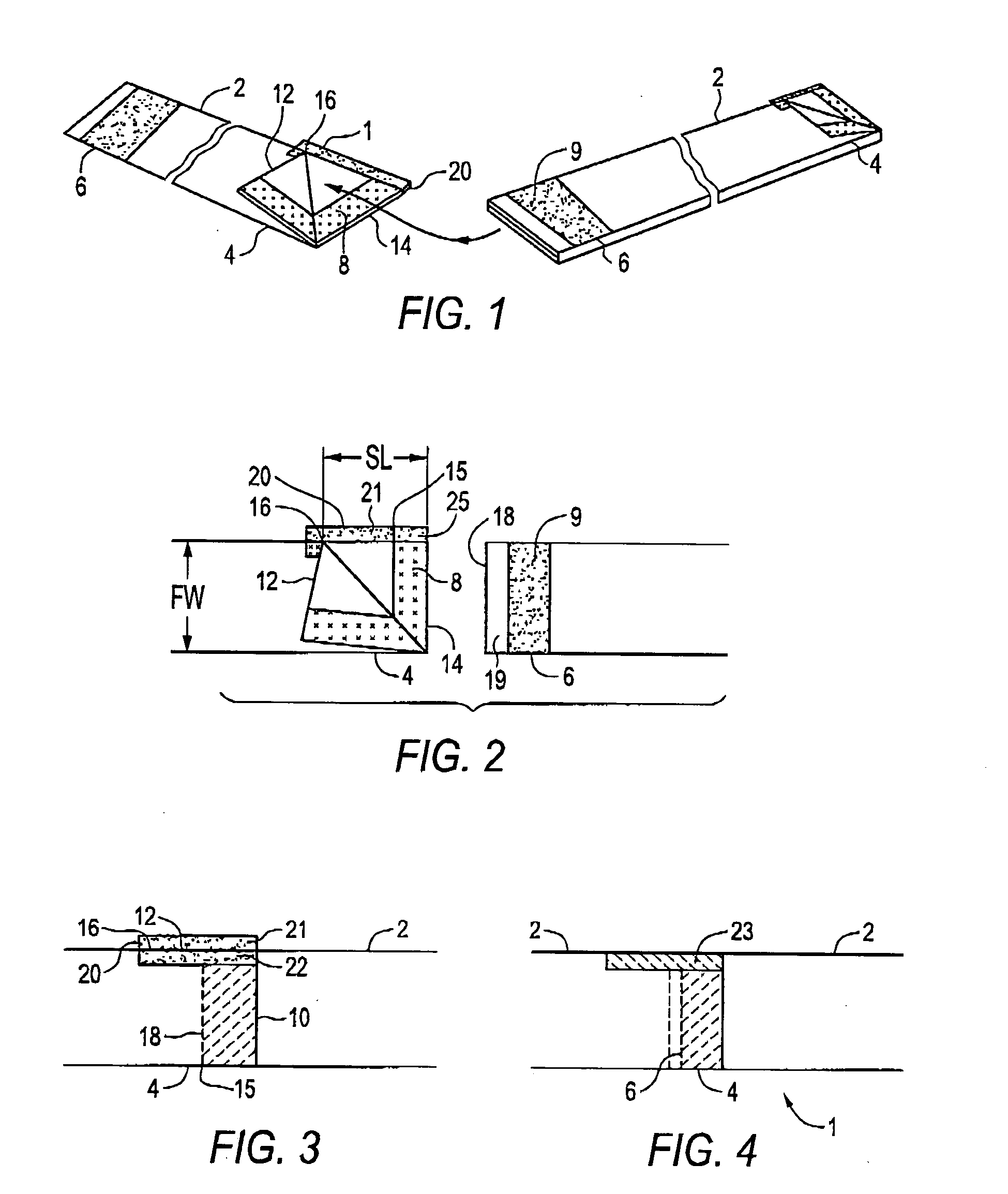
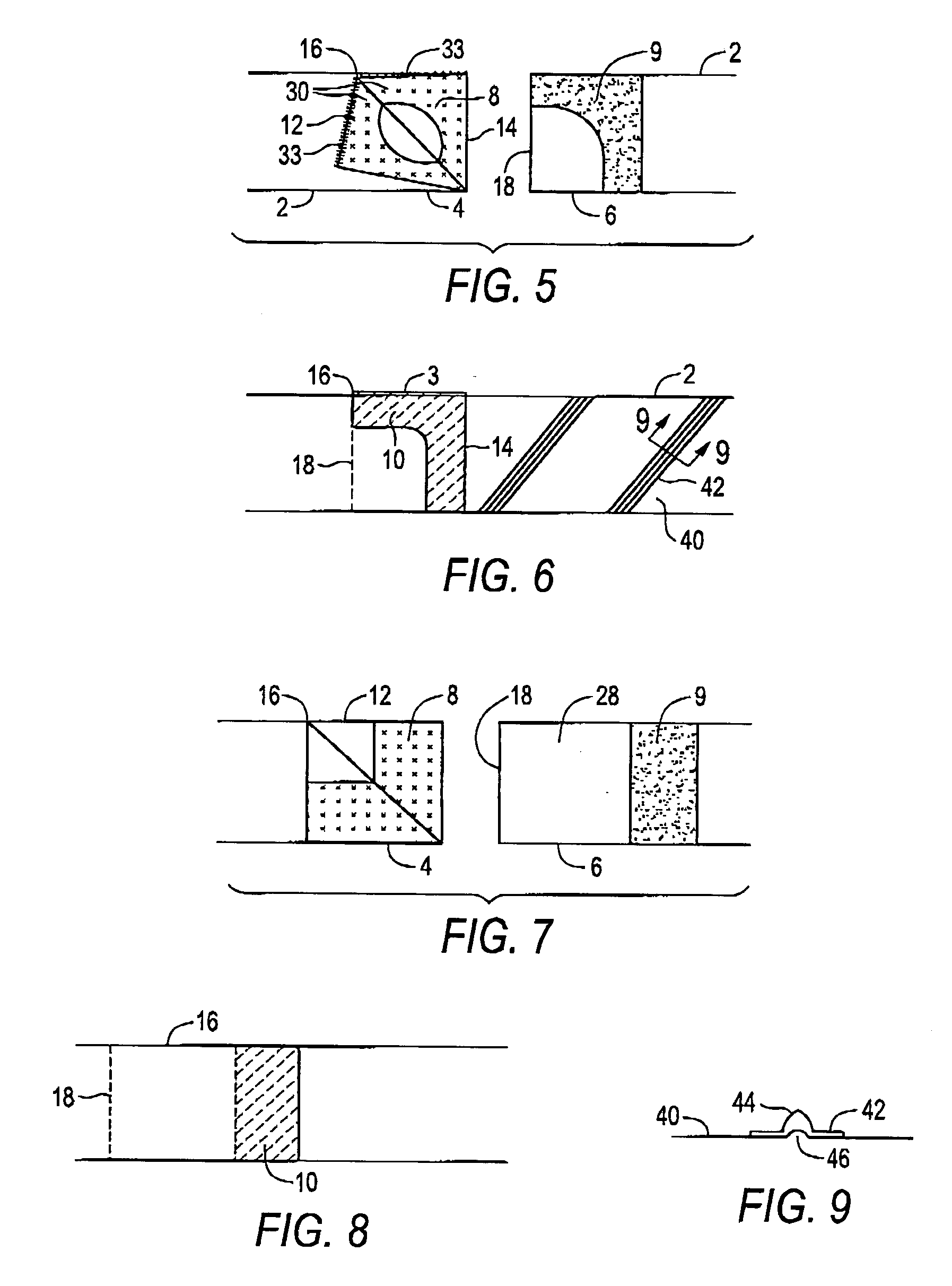
[0025]FIG. 1 illustrates a plurality of hose sections 2, each hose section 2 having, at one end a female portion 4 and at an opposite end a male portion 6. As illustrated in FIG. 4, the male portion of one hose section 2 is coupled inside the female portion 4 of an adjacent hose section 2 to form a flexible hose apparatus 1.
[0026] A first element 8 of a hook and loop coupling fastener 10 is attached to an inside surface of the female portion 4, and a corresponding second element 9 of the hook and loop coupling fastener 10 is attached to an outside surface of the male portion 6. FIG. 3 illustrates schematically the first and second elements 8, 9 engaging to form the hook and loop coupling fastener 10. One of a hook or a loop element is located as the first element 8, and the other as the second element 9.
[0027] A single slit 12 extends from the end edge 14 of the female portion 4 longitudinally along the hose section 2 to a slit end 16. The balance of the end edge 14 of the female portion 4 is unbroken and contiguous from one side of the slit 12 to an opposite side of the slit 12. Thus there is only one area in the coupling of the invention where air can leak out, as opposed to the prior art hook and loop fastener comprising two slits.
[0028] In the embodiment illustrated in FIGS. 1-4, the first element 8 of the hook and loop coupling fastener 10 extends from substantially the end edge 14 of the female portion 4 to a coupling terminus 15 part way along the slit 12. The male portion 6 is inserted into the female portion 4 such that the end edge 18 of the male portion 6 is located between the coupling terminus 15 and the slit end 16. The area of the inside of the female portion 4 covered by the first element 8 corresponds substantially to the area of the outside of the male end 6 covered by the second element 9, and the end portion 19 of the male portion 6 is bare of the second element 9 of hook and loop coupling fastener 10.
[0029] The female portion 4 has a flat width FW when laid flat as in FIG. 2, and for ease of coupling the slit 12 has a length SL such that the slit end 16 is located a distance that is more than one half of the flat width FW from the end edge 14 of the female portion 4. A shorter slit will offer some improvement in ease of coupling, however it is contemplated that a slit length SL of one half to three quarters of the flat width FW will be generally used in practice.
[0030] Thus in the embodiment of FIGS. 1-4 the first and second elements 8, 9 of the hook and loop coupling fastener 10 are in a narrow band at the end of the female portion 4. The slit 12 extends considerably farther along the female portion 4 than the hook and loop coupling fastener 10 such that when the female portion 4 is spread open along the slit, it is relatively easy to insert the male portion 6 to a midpoint of the slit 12 where the end edge thereof is between the coupling terminus 15 and the slit end 16. The great majority of the second element 8 is exposed when the female portion 4 is spread open along the slit 12 as illustrated in FIG. 2, such that only a minor amount of tucking is required to properly position the male portion 6 inside the opened female portion 4.
[0031] The hook and loop elements of the hook and loop coupling fastener 10 grab each other during the positioning process such they must be disengaged for correction of positioning. The less the area of hook and loop coupling fastener 10, the more easily the coupling can be accomplished.
[0032] To prevent air leakage in the embodiment of FIGS. 1-4, a flap 20 is attached to the outside surface of the female portion 4 along a first side of the slit 12. A first element 21 of a hook and loop flap fastener 23 is attached to an inner face 25 of the flap 20, and a second element 22 of the hook and loop flap fastener 23 is attached to the outside surface of the female portion 4 along an opposite second side of the slit 12.
[0033] The flap 20 is oriented such that the first element 21 of the hook and loop flap fastener 23 on the inner face 25 of the flap 20 can be pressed against the second element 22 of the hook and loop flap fastener 23 to cover the slit 12, as illustrated in FIG. 4. The illustrated flap 20 can be incorporated into any of the other illustrated embodiments as well where further security of sealing is desired. The illustrated flap 20 and the second element 22 of the hook and loop coupling fastener 23 extend from the end edge 14 of the female portion 4 beyond the slit end. By extending the flap 20 and hook and loop flap fastener 23 beyond the slit end 16, better sealing is provided. In prior art couplings with two slits, the flap 20 ends at the slit end 16, and the end edge 18 of the male portion 6 is also located at the slit end 16. Air leakage occurs at this point through the end of each of the pair of slits in the prior art since there is essentially a hole at this point where the flap, slit, and male portion meet.
[0034] By reducing the number of slits to one in the present invention, this air leakage is reduced by one half. By extending the flap 20 beyond the slit end 16, leakage is further reduced. Alternatively or in addition, the male portion 6 may also be extended past the slit end 16, as illustrated in the embodiment of FIGS. 7 and 8.
[0035] In the embodiment of FIGS. 5 and 6, to facilitate the ease of coupling, the first element 8 of the hook and loop coupling fastener 10 extends from the end edge 14 to the slit end 16 only along first and second portions 30 of the inside surface of the female portion 4 on each side of the slit 12. Farther away from the slit 12, a substantial portion of the hook and loop coupling fastener 10 is removed, making it easier to position the male and female portions 4, 6 properly with respect to each other since there is less hook and loop fastener material to maneuver, as discussed above.
[0036] Thus in the embodiment of FIGS. 5 and 6 the hook and loop coupling fastener 10 seals the slit 12 by providing an engaged hook and loop fastener adjacent to both sides of the slit 12. At the same time, a sufficiently strong coupling is provided to prevent the hose sections 2 from separating when conducting pressurized air in some instances. A zip fastener 33 is also illustrated to further secure the coupling against leakage and separation.
[0037]FIGS. 8 and 9 illustrate an alternate embodiment wherein the male portion 6 extends into the female portion 4 beyond the slit end 16, and an end portion 28 of the male portion 4 has an outer surface that is bare of the second element 9 of the hook and loop coupling fastener 10, As illustrated the first and second elements 8, 9 form a hook and loop coupling fastener 10 that ends at a midpoint of the slit 12, similar to the embodiment of FIGS. 1-4. Contrary to the embodiment of FIGS. 1-4, the end edge 18 of the male portion 6 extends a substantial distance past the slit end 16. Air pressure inside the hose apparatus 1 will press the male portion 6 against the inside of the female portion 4 to provide a seal that could be satisfactory for some applications providing. A flap or zipper could be added as well to reduce leakage further.
[0038] A typical application will see the air hose apparatus 1 adapted at one end thereof for attachment to a pressurized air supply at an airport gate, and adapted at an opposite end thereof for releasable attachment to an aircraft ventilation system. Pressures in such an application are typically about one pound per square inch.
[0039]FIG. 5 illustrates a wear strip 42 attached around a circumference of an outside surface 40 of a hose section 2 by welding. Adhesives could also be used if desired or convenient in a particular application. In this way no holes are made in the hose section 2, as is the case with sewing, and so air leakage is reduced. As illustrated in FIG. 9, the wear strip 42 comprises a raised central portion comprising a solid bumper strip 44 with a hollow central portion 46 under the solid bumper strip 44. The solid bumper strip 44 provides for longer wear than prior art wear strips where the strip is made simply by forming a strip of plastic of constant thickness into a strip with a raised bump in the middle. The thin plastic wears out quickly when dragged across a rough surface such as an airport tarmac.
[0040] In operation, the method for coupling a plurality of hose sections 2 together to form a flexible air hose apparatus 1 comprises opening the female portion 4 by spreading the slit 12, inserting the male portion 6 of an adjacent hose section 2 into the female portion 4 such that the first and second portions 8, 9 of the hook and loop coupling fastener 10 are substantially aligned, and pressing the female portion 4 against the male portion 6 to engage the first element 8 of the hook and loop coupling fastener 10 to the second element 9 of the hook and loop coupling fastener 10 while aligning edges of the slit 12. This will most conveniently be accomplished by laying the hose sections 2 flat adjacent one another, as illustrated.
[0041] In the embodiment comprising a flap 20, the inner face 25 of the flap 20 is moved such that the first element 21 of the hook and loop flap fastener 23 engages the second element 22 of the hook and loop flap fastener 23 to cover the slit 12 and reduce air leakage.
[0042] The foregoing is considered as illustrative only of the principles of the invention. Further, since numerous changes and modifications will readily occur to those skilled in the art, it is not desired to limit the invention to the exact construction and operation shown and described, and accordingly, all such suitable changes or modifications in structure or operation which may be resorted to are intended to fall within the scope of the claimed invention.

PUM

no PUM

Description & Claims & Application Information

We can also present the details of the Description, Claims and Application information to help users get a comprehensive understanding of the technical details of the patent, such as background art, summary of invention, brief description of drawings, description of embodiments, and other original content. On the other hand, users can also determine the specific scope of protection of the technology through the list of claims; as well as understand the changes in the life cycle of the technology with the presentation of the patent timeline. Login to view more.

Similar technology patents

Air conditioner chassis structure and air conditioner

PendingCN109974275AEfficient water collectionReduce air leakage
Owner:NINGBO AUX ELECTRIC +1

Sealing ring of piston of air cylinder

InactiveCN103511623AReduce air leakageImprove work efficiency
Owner:WUHU EDISON AUTOMATION EQUIP

Rotary nozzle ring capable of reducing ventilation resistance for medium-speed coal pulverizer

PendingCN110801932AReduce air leakageReduced slag discharge
Owner:CHANGCHUN POWER GENERATION EQUIP PLANT

System and method for correcting turbo lack and vehicle

PendingCN111197527AReduce air leakagereduce fuel consumption
Owner:HYUNDAI MOTOR CO LTD +1

Movable vacuum environment-friendly toilet with large suction force

ActiveCN111877811Areduce air leakageExtension of time
Owner:天正浚源环保科技有限公司

Classification and recommendation of technical efficacy words

  • convenient to use
  • reduce air leakage

Mobile communication device

InactiveUS20070191078A1convenient to use
Owner:SAMSUNG ELECTRONICS CO LTD

Magnetic beverage holder

InactiveUS20050056655A1convenient to use
Owner:GARY LONNIE F

Security system

InactiveUS20060056664A1time be prolonged and shortenconvenient to use
Owner:FUJIFILM CORP +1

Annular sintering machine for water seal

ActiveCN103983111AImprove the sealing effectReduce air leakage
Owner:SHANDONG PROVINCE METALLURGICAL ENG CO LTD

Machine room refrigerating system and air conditioner air volume adjusting and control method and device

PendingCN108917109Areduce time delayReduce air leakage
Owner:EMERSON NETWORK POWER CO LTD

Cutting machine with retractable curtains

ActiveCN105881633Areduce air leakageSimplify the substructure
Owner:NANJING VOCATIONAL UNIV OF IND TECH

Hinge type air preheating sealing device

InactiveCN103900099AReduce air leakageGood sealing effect
Owner:周惠

Grouping type machine room cabinet of integrated signal circuit

InactiveCN108718503Areduce air leakageprevent dust
Owner:周楚楚
Why Eureka
Try Eureka