Extensible modular luminaire

a modular luminaire and luminaire housing technology, applied in the field of modular luminaires, can solve the problems of difficult mounting or installation, difficult replacement of lamps, and crooked or challenged rows of linear lighting made by assembling individual luminaire housings, and achieve the effects of convenient installation and service, convenient separation, and new ease of installation

Inactive Publication Date: 2005-03-03
EPPLER ROSS ROBERT
View PDF3 Cites 12 Cited by
  • Summary
  • Abstract
  • Description
  • Claims
  • Application Information

AI Technical Summary

Benefits of technology

[0009] The present invention overcomes the drawbacks inherent in prior art, offering unique features that provide consumers, contractors, and designers with new ease of installation, and ability to customize appearance and function using standardized modular components.
[0010] An object and advantage of the present invention is to provide a linear luminaire that is easily installed and serviced, even when used in very small coves or suspended for indirect lighting.
[0011] A further object and advantage of the present invention is to provide a luminaire with an extensible housing that is substantially self-supporting when made e

Problems solved by technology

Energizing components had to be serviced in place, even when the luminaire was far from reach, or not readily accessible.
Housings were bulky, heavy, and difficult to mount or install.
Long rows of linear lighting made by assembling individual luminaire housings typically were crooked or

Method used


Image

  • Extensible modular luminaire
  • Extensible modular luminaire
  • Extensible modular luminaire

Examples


Embodiment Construction

[0046] Basic Housing

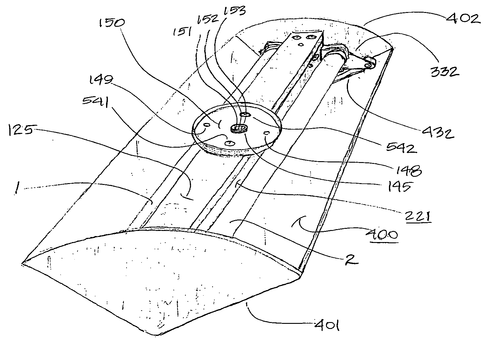
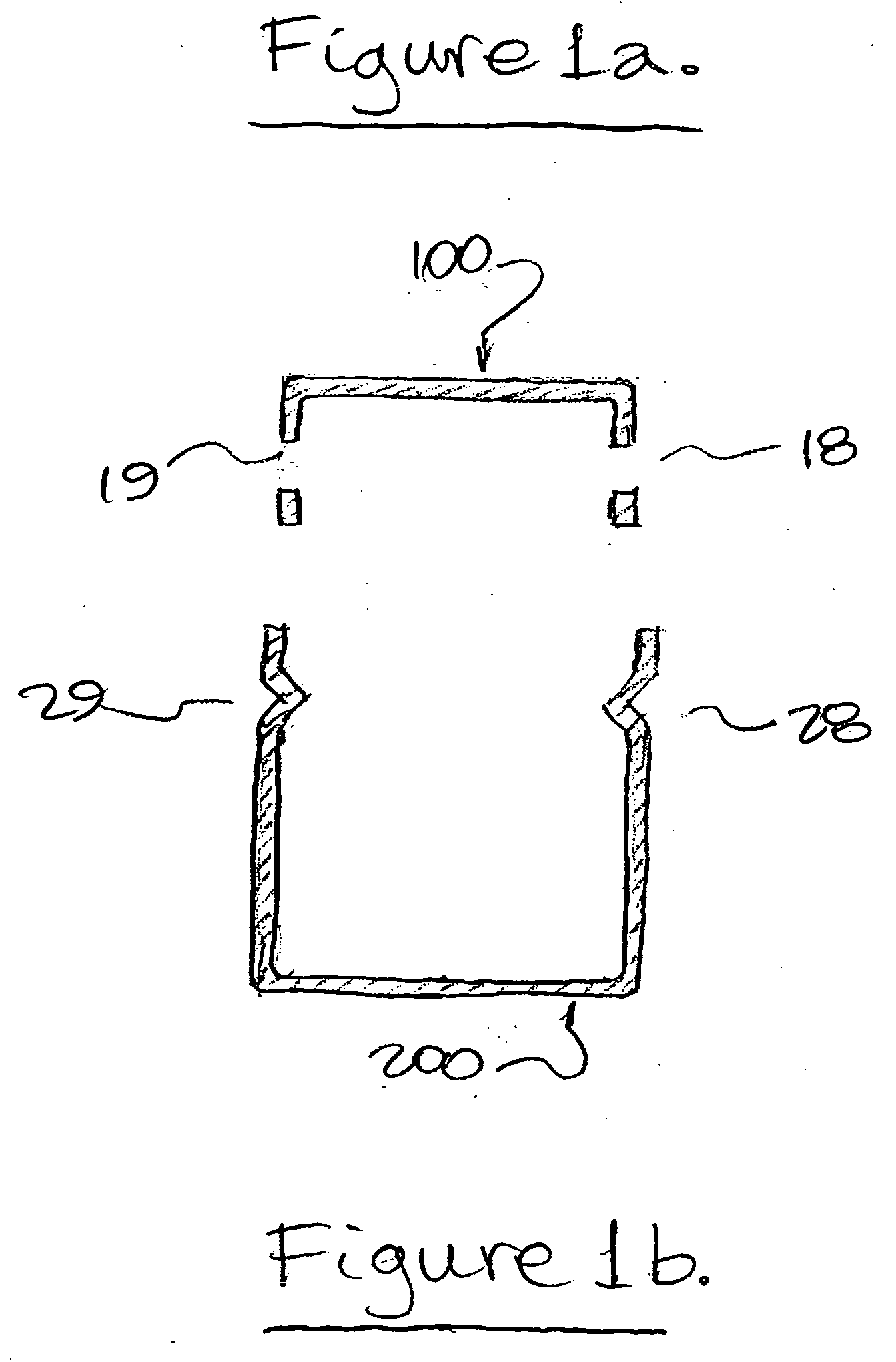
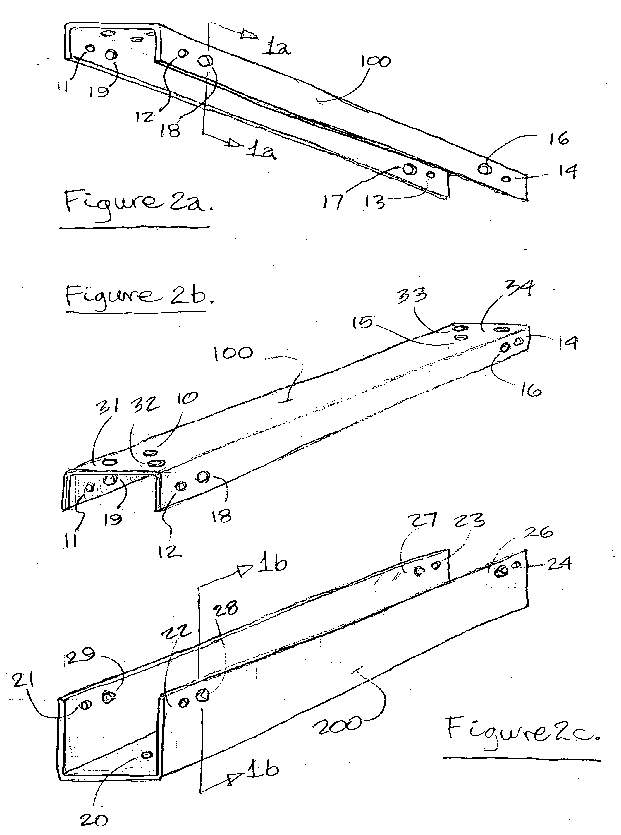
[0047]FIGS. 1a, 1b, 2a, 2b, and 2c, show two parts that when assembled, comprise a luminaire housing, as shown in FIGS. 3a, 3b, and 4. An inverted-U-shaped basic mounting track (100), for mounting and supporting the assembled luminaire and supporting appendages, is shown in FIGS. 1a, 2a, and 2b. A similarly sized U-shaped basic channel (200), for supporting luminous components, is shown in FIGS. 1b and 2c. The track and channel lengths are much greater than their widths or heights. Both are substantially square-cornered. Both have thin walls made of material that is stiff, but not entirely rigid.

[0048] The track has two sides and a top, and the channel has two sides and a bottom. The track is narrower than the channel, and the channel is taller than the track. The inside distance between the lower edges of the sides of the channel is the same as the outside distance between the track's sides. The channels corners are formed to slightly less than ninety degree i...


PUM


Abstract

A linearly extensible modular luminaire comprised of mounting tracks (100,180) and translationally offset overlapping channels (211,212), with incorporated luminous means, alone or along with hangers (331,332,731) that provide support for cover brackets (431,731) that are attached to light modifying coverings (400,900), and wherein linearly radiated light is distributed directly, or in combination with coverings indirectly or modified, when connected with a source of power and energized. Also, the modular luminaire that is not extensible but otherwise comprised of same components not translationally offset, permitting the construction of a wide variety of luminaires, such as the one in FIG. 11, that incorporates a canopy (150) for mounting over lighting outlet boxes.

Description

CROSS-REFERENCE TO RELATED APPLICATIONS [0001] The reader is directed to the Provisional Patent Application [0002] File Number: Ser. No. 60 / 488999 [0003] Filing date 22 Jul. 2004 [0004] Titled Customizable Modular LuminaireBACKGROUND OF THE INVENTION [0005] After the invention of the light bulb, many innovators devised light sources, and luminaires for supporting and operating them, that produced light which radiated from an axis, rather than just a point. A variety of means for diffusing, reflecting, or altering the light from these sources were employed. Linear incandescent lamps persisted, but fluorescent tube lighting largely took over linear applications. Light emitting diodes used for indicators later were also used for illumination, including linearly. [0006] Numerous types of housings supported the light source and energizing components. The fixture housing, type of light source, and light modifiers were wed by design. Energizing components had to be serviced in place, even ...

Claims


Application Information

Patent Timeline
IPC IPC(8): F21V15/01F21V19/00
CPCF21V15/01F21Y2103/00F21V19/0095
Inventor EPPLER, ROSS ROBERT
Owner EPPLER ROSS ROBERT
Why Eureka
Try Eureka