
Method and apparatus for scheduling asynchronous transmissions

Inactive Publication Date: 2005-03-03
GOOGLE TECH HLDG LLC
View PDF20 Cites 23 Cited by
  • Summary
  • Abstract
  • Description
  • Claims
  • Application Information

AI Technical Summary

Benefits of technology

[0010] In at least a still further embodiment, selecting two or more subscriber units having the highest scheduling priority includes selecting the subscriber unit from the list having the highest scheduling priority and selecting at least another subscriber unit from the list, which minimizes the offset differential.

Problems solved by technology

However, because line of sight transmissions are not always possible for base stations that might be located within buildings or tunnels, or base stations that may be located under the ground, sometimes the time synchronization of the base stations is not always readily accommodated.
However, asynchronous transmissions are not without their own set of concerns.
For example, the timing of uplink transmissions in an environment supporting autonomous scheduling by the individual subscribers can be quite sporadic and / or random in nature.
Furthermore, in the event of a collision, there is spare bandwidth available to accommodate the need for any retransmissions.
However, as traffic volume increases, the likelihood of data collisions (overlap) also increases.
The need for any retransmissions also correspondingly increases, and the availability of spare bandwidth to support the increased amount of retransmissions correspondingly diminishes.
However even with explicit scheduling, given the disparity of start and stop times of asynchronous communications and more particularly the disparity in start and stop times relative to the start and stop times of different uplink transmission segments for each of the non-synchronized base stations, gaps and overlaps can still occur.

Method used


Image

  • Method and apparatus for scheduling asynchronous transmissions
  • Method and apparatus for scheduling asynchronous transmissions
  • Method and apparatus for scheduling asynchronous transmissions

Examples


Embodiment Construction

)

[0025] While the present invention is susceptible of embodiment in various forms, there is shown in the drawings and will hereinafter be described presently preferred embodiments with the understanding that the present disclosure is to be considered an exemplification of the invention and is not intended to limit the invention to the specific embodiments illustrated.

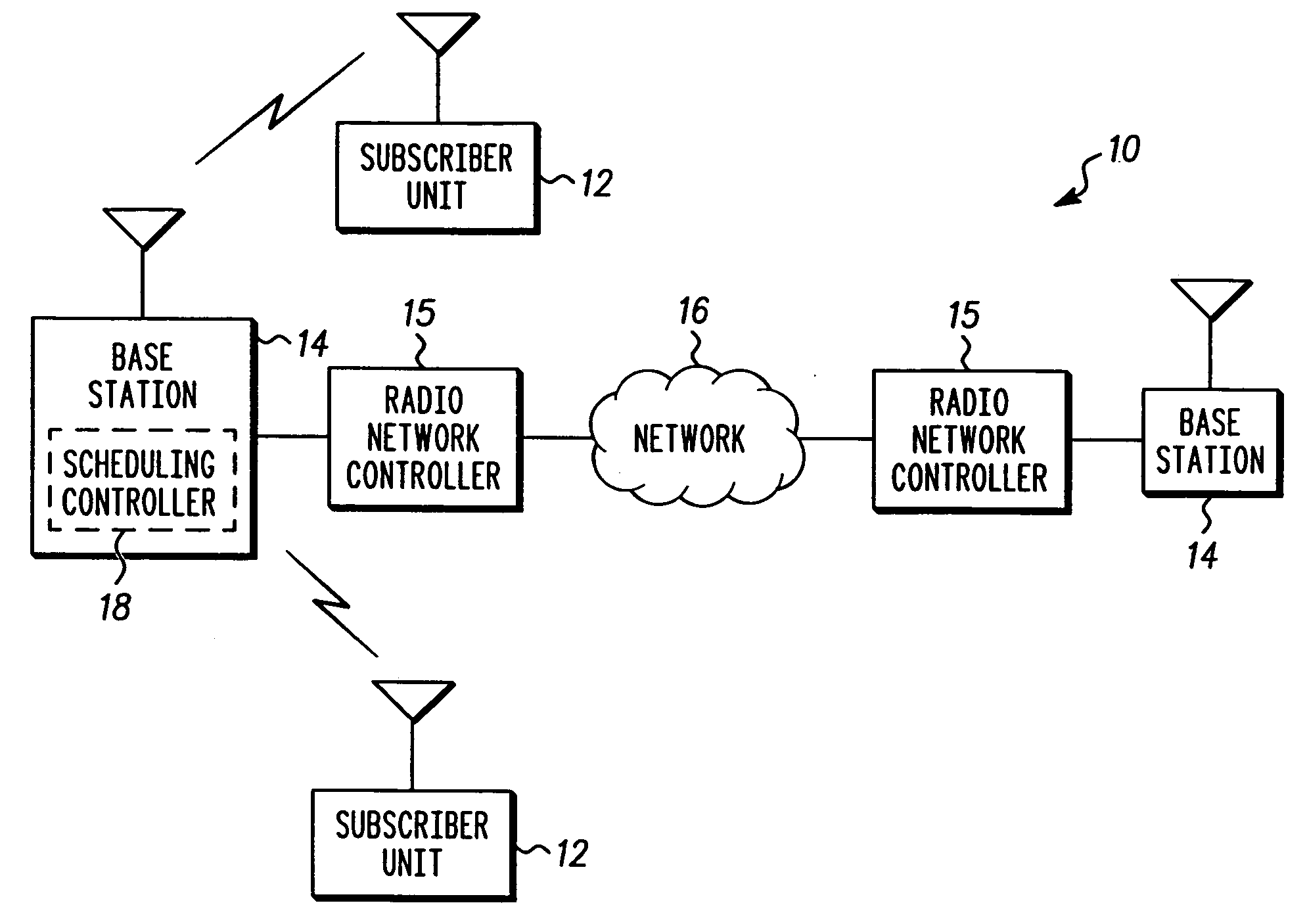
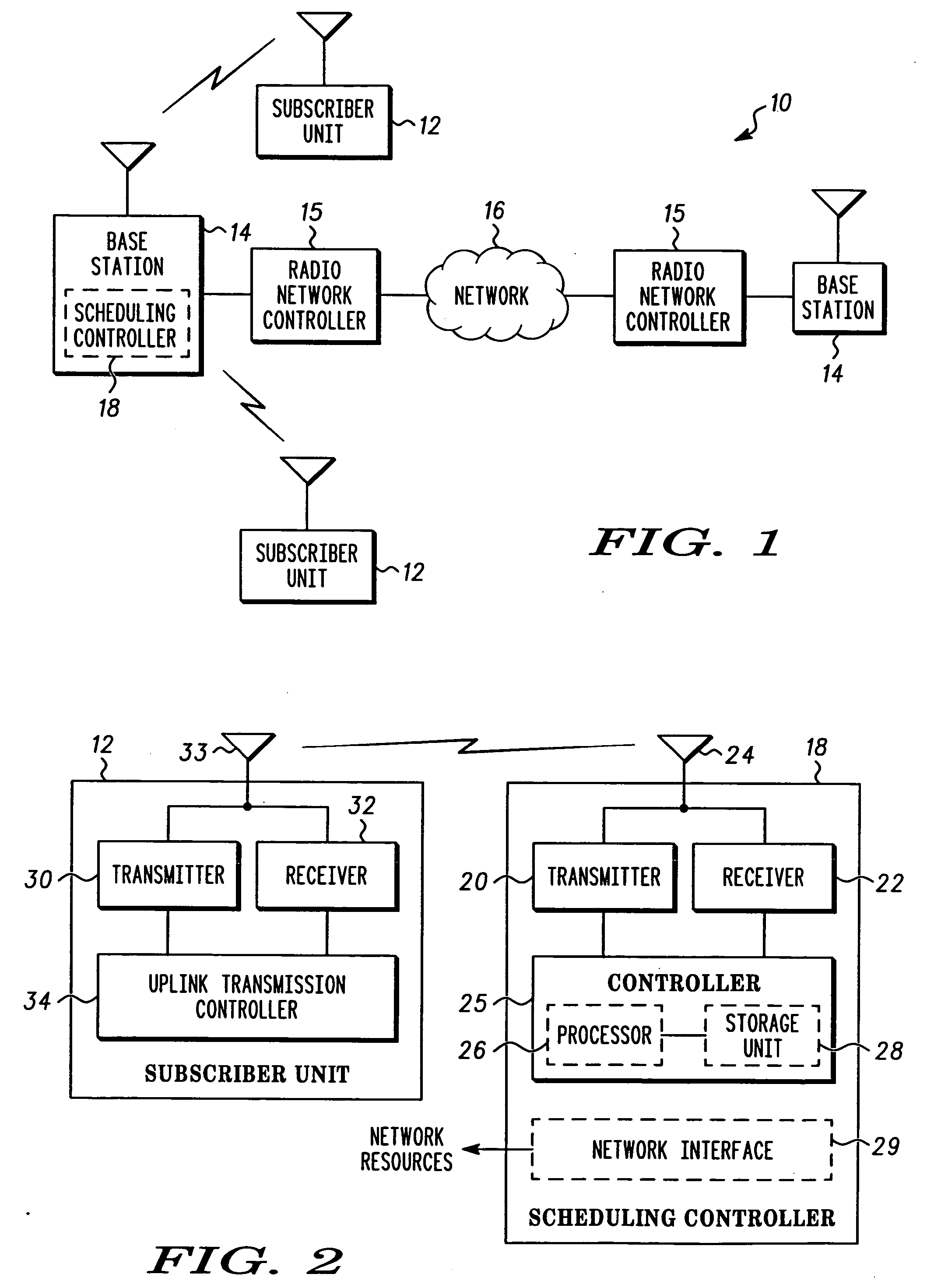
[0026]FIG. 1 illustrates at least one example of an asynchronous wireless communication network 10 in which it would be suitable to incorporate the present invention. Examples of asynchronous wireless communication networks include networks, which conform to several well known standards including Global System for Mobile Communications (GSM) and Wide band CDMA (WCDMA).

[0027] The communication network 10 illustrates a pair of subscriber units 12, which communicate with at least one of a pair of base stations 14. In the same or alternative embodiments, a subscriber unit can be sometimes alternatively referred to as User...


PUM


Abstract

The present invention provides a method of scheduling asynchronous transmissions for a plurality of subscriber units. The method includes receiving information associated with a plurality of subscriber units that have uplink data to transmit, the information including uplink timing offset information associated with each of the subscriber units. Two or more subscriber units are then selected from a set of subscriber units having a timing offset differential, that is below a predetermined threshold, where the timing offset differential is the difference between the timing offset of a first subscriber unit and the timing offset of a second subscriber unit further selectively offset by a multiple of the transmission segment size, which minimizes the difference. The transmission segments, which are available for the uplink of data, are then allocated between the selected two or more subscriber units, which limits the number of transmission segments that have at least one of an overlap or a gap, and the amount of any overlap or gap, in order to minimize wasted scheduling opportunities.

Description

FIELD OF THE INVENTION [0001] The present invention relates generally to scheduling asynchronous transmissions and, more particularly, to scheduling asynchronous transmission, based upon timing offset information received for each of the subscriber units. BACKGROUND OF THE INVENTION [0002] Wireless communication systems are commonly put in place to provide voice and data communications. These systems often are deployed in accordance with one or more of several well known standards, which have been developed to more readily allow for the interoperability of equipment produced by different manufacturers. While earlier systems were more principally concerned with voice communications, there has been a more recent effort to increasingly accommodate the transmission of data at ever increasing rates. [0003] Several third generation standards have emerged, which attempt to accommodate the anticipated demands for increasing data rates. At least some of these standards support synchronous co...

Claims


Application Information

Patent Timeline
IPC IPC(8): H04L12/56H04W56/00H04W72/04H04W72/08H04W72/12H04W84/04
CPCH04W56/0045H04W84/04H04W72/0446H04W72/12H04L5/0058
Inventor LOVE, ROBERT T.GHOSH, AMITAVAKUCHIBHOTLA, RAVI
Owner GOOGLE TECH HLDG LLC
Learn More