Valve actuation apparatus of internal combustion engine

Inactive Publication Date: 2013-01-24
HITACHI AUTOMOTIVE SYST LTD
View PDF1 Cites 2 Cited by
  • Summary
  • Abstract
  • Description
  • Claims
  • Application Information

AI Technical Summary

Benefits of technology

[0006]It is, therefore, in view of the previously-described disadvantages of the prior art, an object of the invention to provide a valve actuation apparatus of an internal combustion engi

Problems solved by technology

This results in an undesirably great difference between a target valve lift amount

Method used


Image

  • Valve actuation apparatus of internal combustion engine
  • Valve actuation apparatus of internal combustion engine
  • Valve actuation apparatus of internal combustion engine

Examples


Example

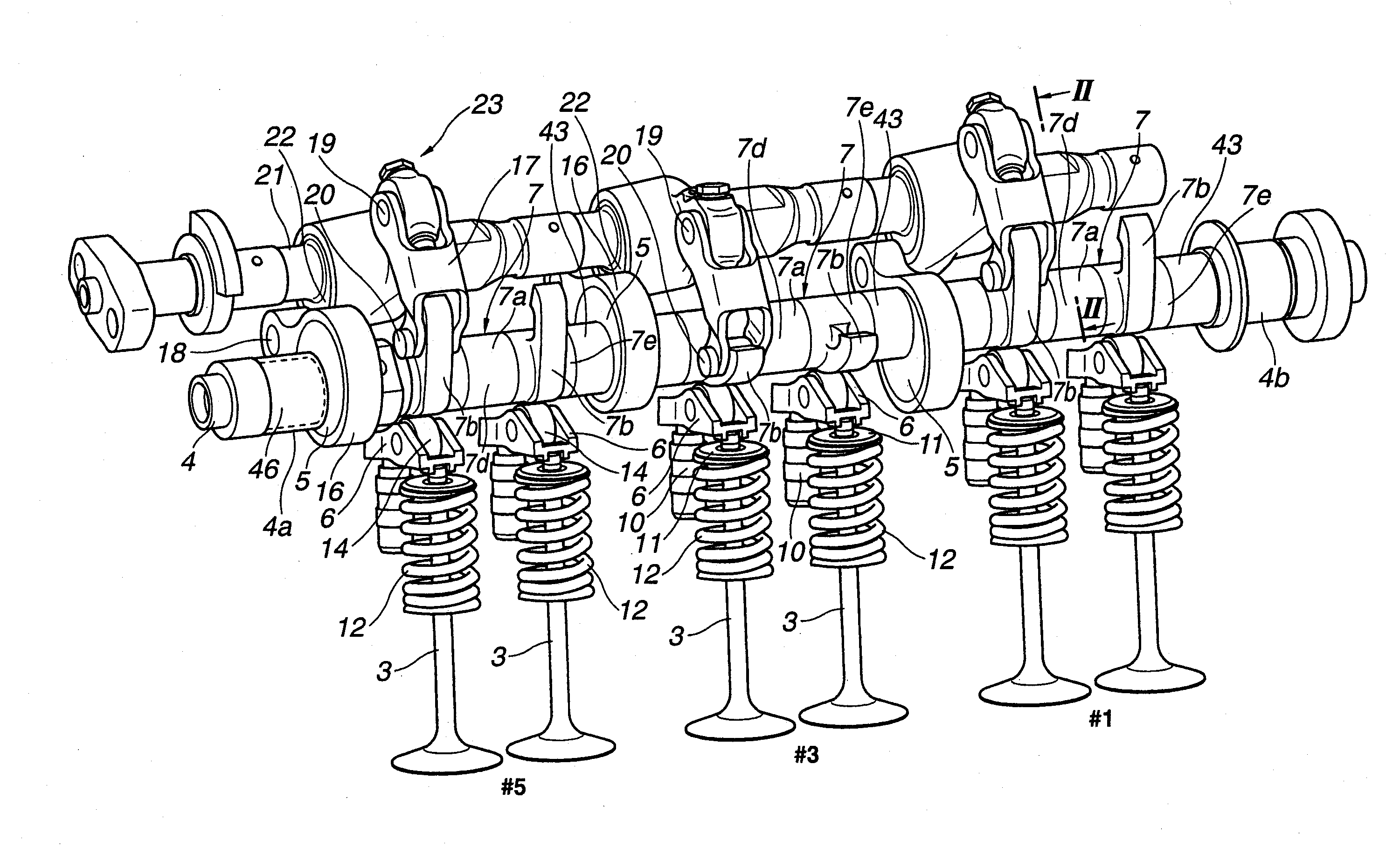
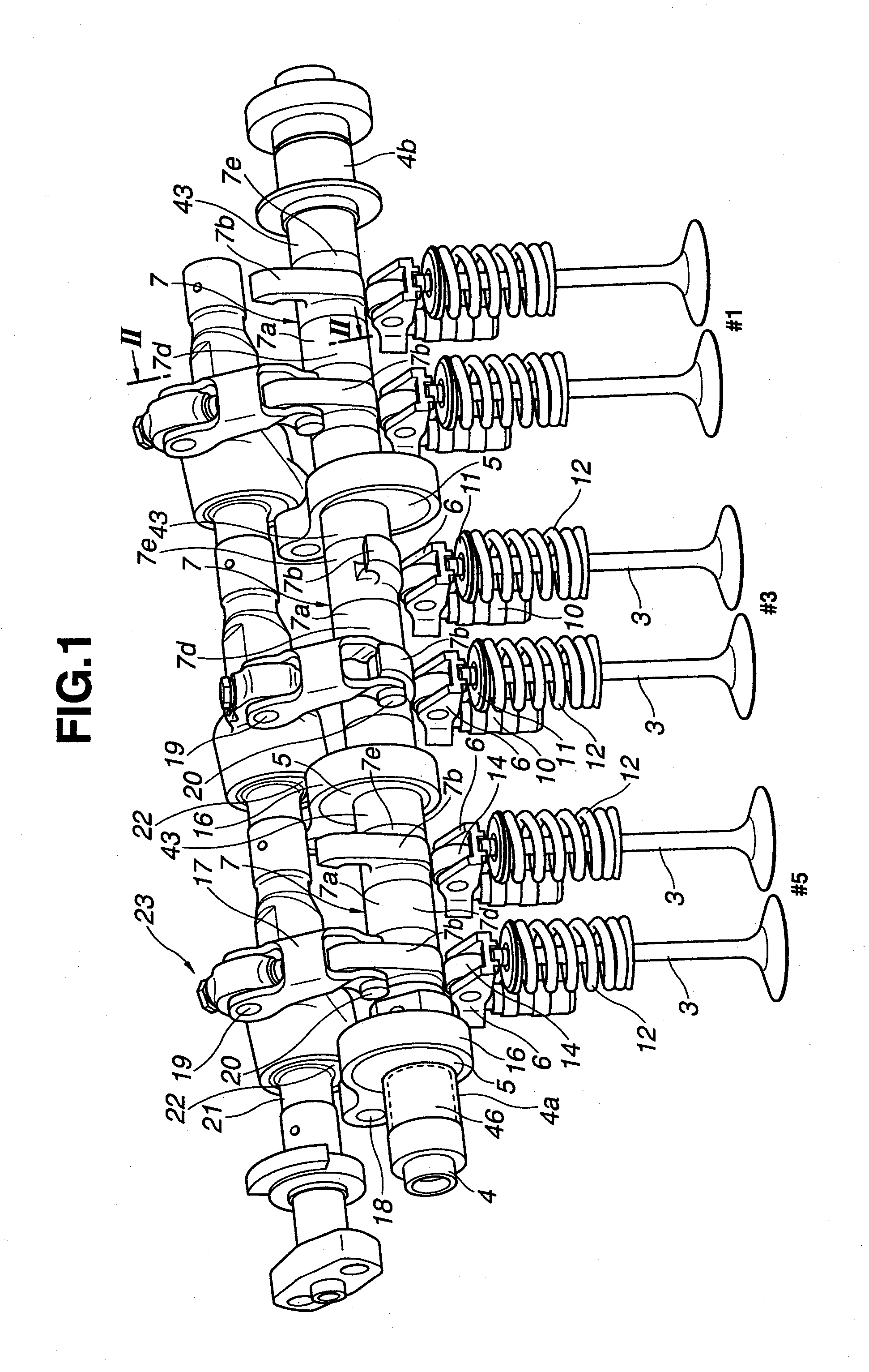
[0018]Referring now to the drawings, the valve actuation apparatus of the embodiment is exemplified in a variable valve event and lift control apparatus of the intake-valve side of a V-6 internal combustion engine whose cylinders are arranged in two banks of three cylinders. In particular, FIGS. 1-4 show the valve actuation apparatus of the embodiment, which is installed on three cylinders (i.e., No. 1 cylinder, No. 3 cylinder, and No. 5 cylinder) of one cylinder bank of the V-6 engine.

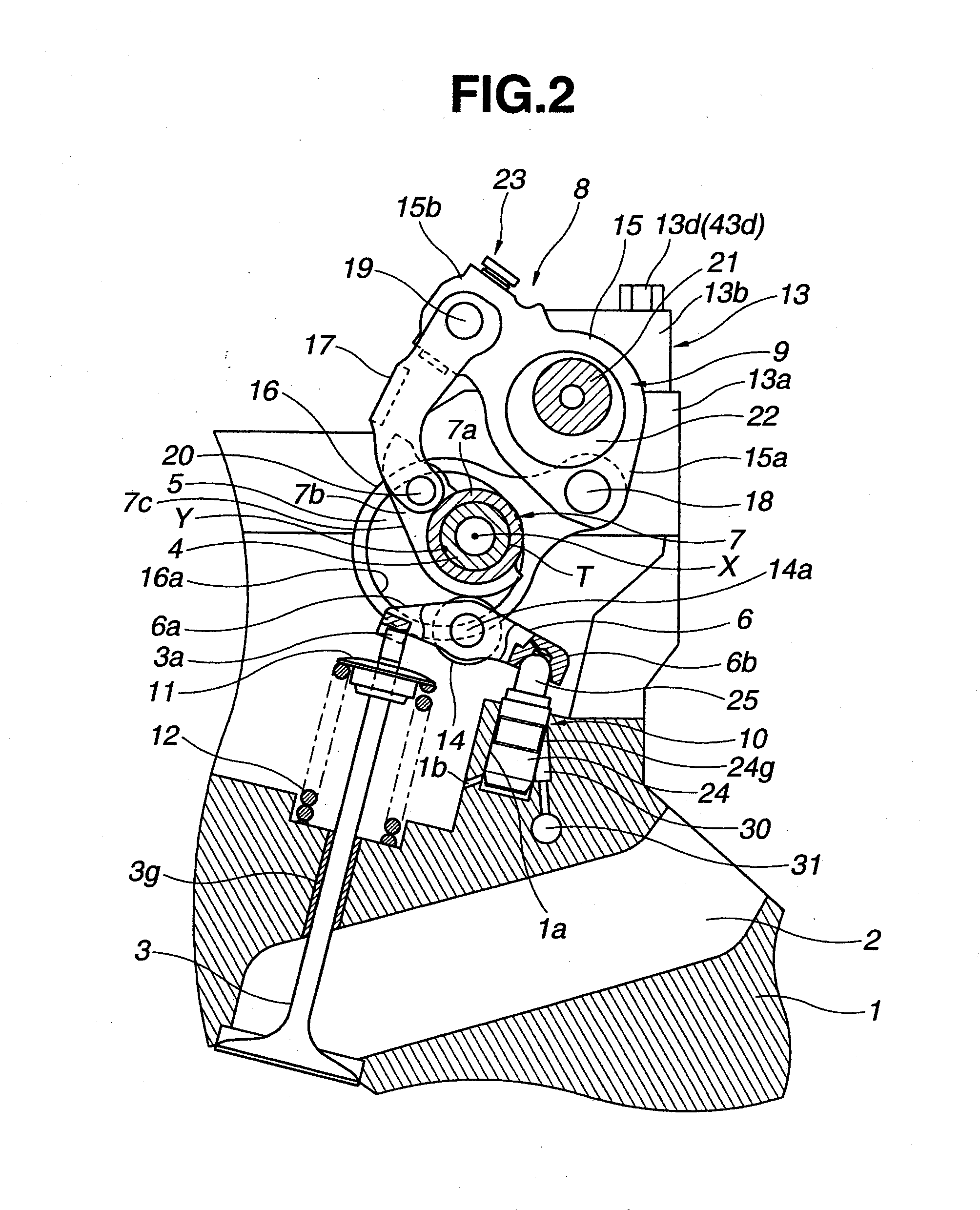
[0019]As clearly shown in FIGS. 1-3, the valve actuation apparatus of the embodiment is provided with two intake valves 3, 3 per cylinder for opening and closing a pair of intake ports 2, 2 formed in a cylinder head 1, a drive shaft 4, a rockable-cam structural member 7, a motion transmission mechanism (or a multi-nodular linkage motion converter) 8, a control mechanism 9, and a pair of hydraulic lash adjusters 10, 10. Drive shaft 4 is located above the three cylinders (#1, #3, #5 cylinders) of one cy...


PUM


Abstract

In a valve actuation apparatus of a multi-cylinder engine employing a drive shaft rotatably arranged to extend over a plurality of cylinders, a drive cam attached to the drive shaft, and a motion transmitter provided for each of the cylinders for converting a rotary motion of the drive cam into an oscillating motion, a rockable-cam structural member is provided for each of the cylinders in a state where a shaft is inserted through inner peripheries of the rockable-cam structural members, for operating engine valves by the transmitted oscillating motion. A plain bearing is provided in at least one axial position between the axially-spaced rockable-cam structural members. An inner periphery of the plain bearing is in contact with an outer periphery of the shaft, whereas an outer periphery of the plain bearing is in contact with an inner periphery of a bearing portion mounted on the engine.

Description

TECHNICAL FIELD[0001]The present invention relates to a valve actuation apparatus of an internal combustion engine configured to variably control valve characteristics such as a valve lift and valve events of an engine valve (intake and / or exhaust valves) depending on an operating condition of the engine.BACKGROUND ART[0002]In recent years, there have been proposed and developed various variable valve actuation apparatus capable of variably controlling valve characteristics (e.g., a valve lift and valve events) depending on an engine operating condition. One such variable valve actuation apparatus has been disclosed in Japanese Patent Provisional Publication No. 2010-163980 (hereinafter is referred to as “JP2010-163980”).[0003]The variable valve actuation apparatus disclosed in JP2010-163980 is provided with a drive shaft, a rockable-cam structural member, a motion transmission mechanism, and a control cam. The drive shaft is arranged in a longitudinal direction of a multi-cylinder ...

Claims


Application Information

Patent Timeline
IPC IPC(8): F01L1/18F01L1/12
CPCF01L1/185F01L1/2405F01L2250/04F01L2013/0073F01L2105/00F01L1/267F01L2305/00
Inventor YAMAZAKI, TETSUOHOSAKA, NORIOMI
Owner HITACHI AUTOMOTIVE SYST LTD
Why Eureka
Try Eureka