Pattern forming apparatus and pattern forming method
- Summary
- Abstract
- Description
- Claims
- Application Information
AI Technical Summary
Benefits of technology
Problems solved by technology
Method used
Image
Examples
first embodiment
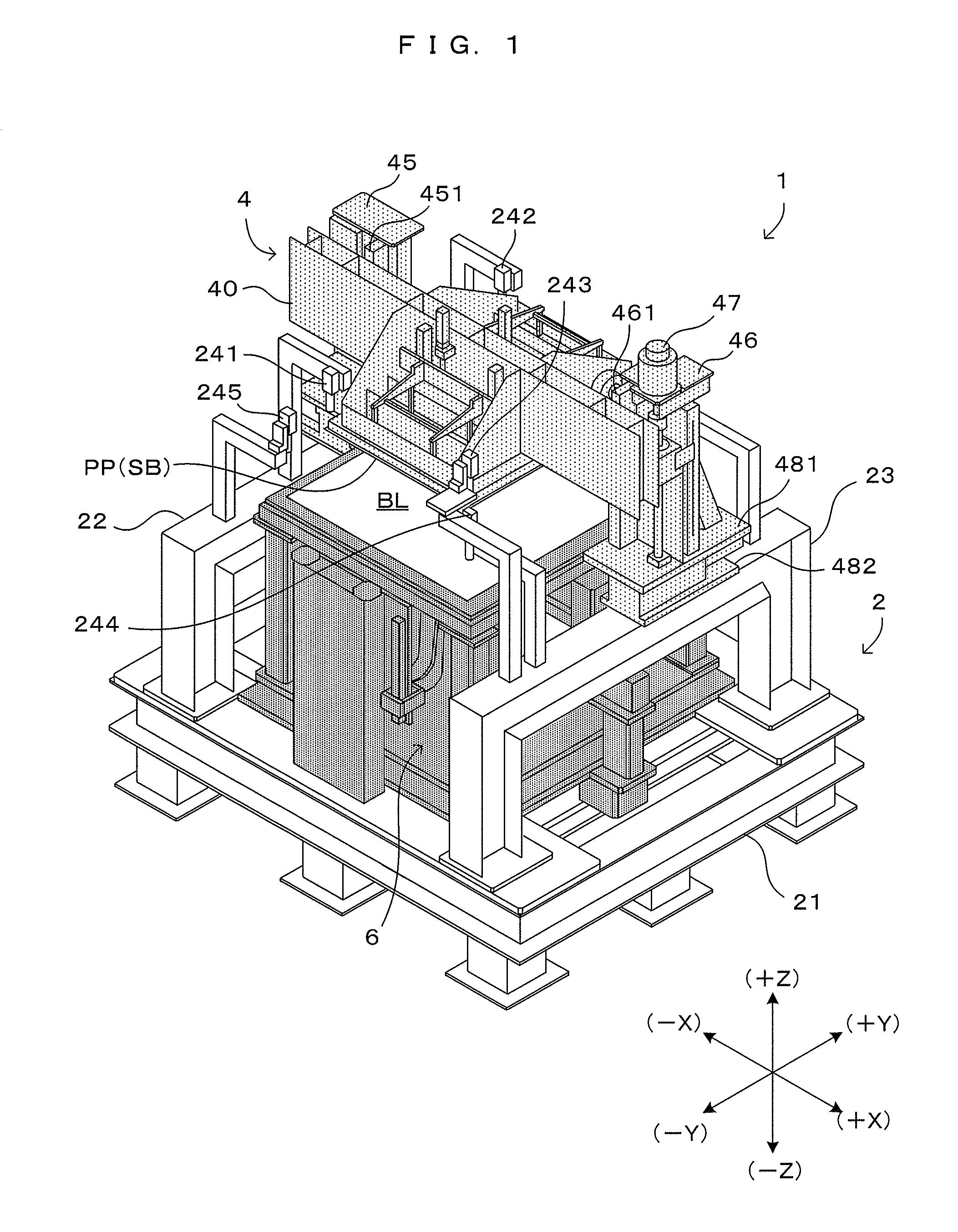
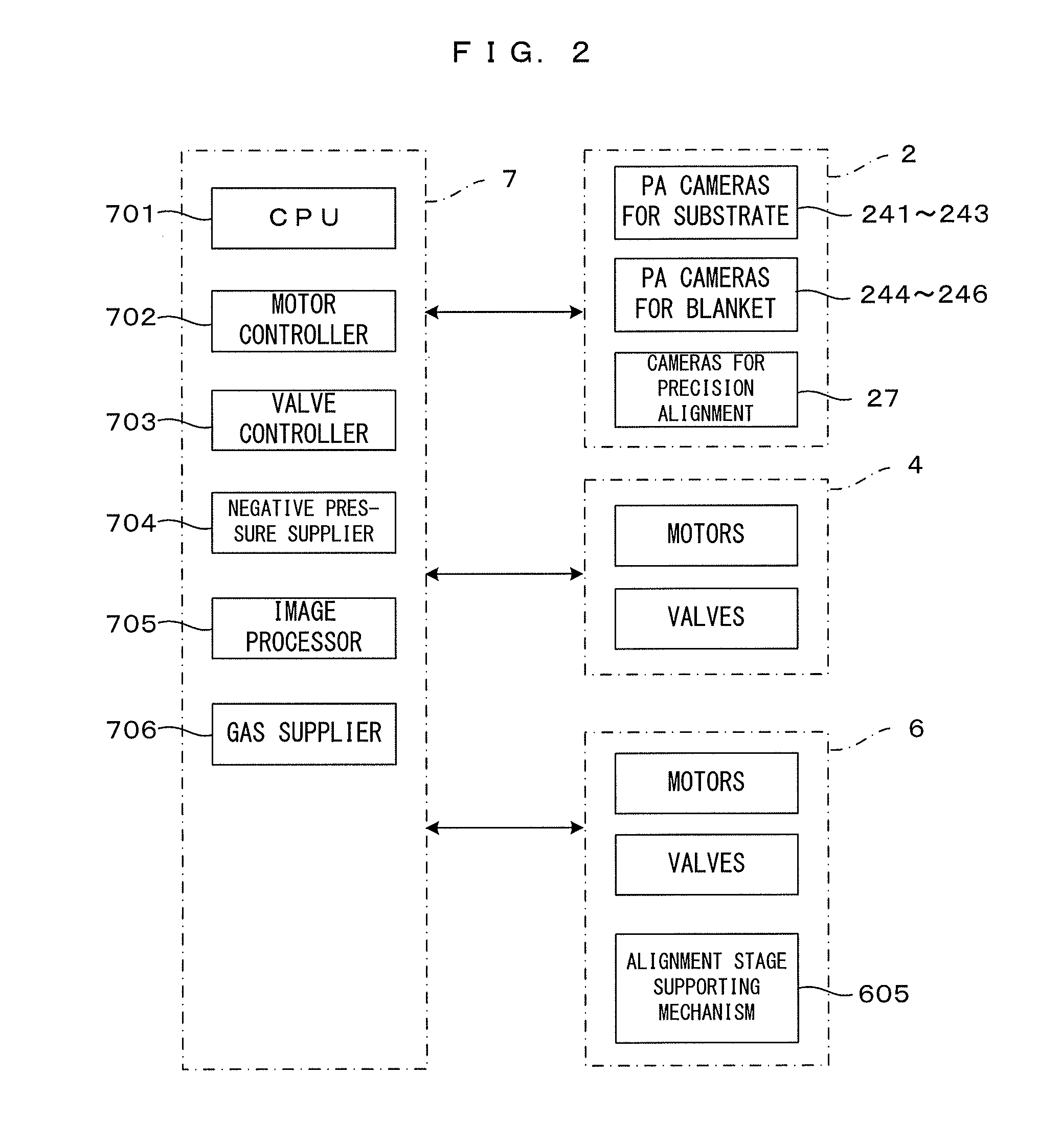
[0044]FIG. 1 is a perspective view which shows a first embodiment of a pattern forming apparatus according to this invention. FIG. 2 is a block diagram which shows a control system of this pattern forming apparatus. Note that a state where an external cover is removed to show the internal configuration of the apparatus is shown in FIG. 1. XYZ orthogonal coordinate axes are set as shown on a right lower side of FIG. 1 to show directions in each figure in a unified manner. Here, an XY plane represents a horizontal plane and a Z axis represents a vertical axis. More specifically, a (+Z) direction represents a vertically upward direction. A forward direction when viewed from the apparatus is a (−Y) direction and an access to the apparatus from the outside including loading and unloading of articles is made in a Y axis direction.
[0045]This pattern forming apparatus 1 is so structured that an upper stage block 4 and a lower stage block 6 are mounted on a main frame 2. In FIG. 1, to clarif...
second embodiment
[0137]Next, a second embodiment of the pattern forming apparatus according to this invention is described. In the pattern forming apparatus of the second embodiment, the structure of a lower stage block partly differs from that of the pattern forming apparatus 1 of the first embodiment described above. On the other hand, other components in the first embodiment, i.e. the main frame 2, the upper stage block 4, the control unit 7 and the like can be basically applied as a main frame, an upper stage block, a control unit and the like in the second embodiment as they are. Accordingly, the following description is centered on points of difference from the first embodiment, particularly the structure and operation of the lower stage block. Further, the same components as in the first embodiment are denoted by the same reference signs and not described.
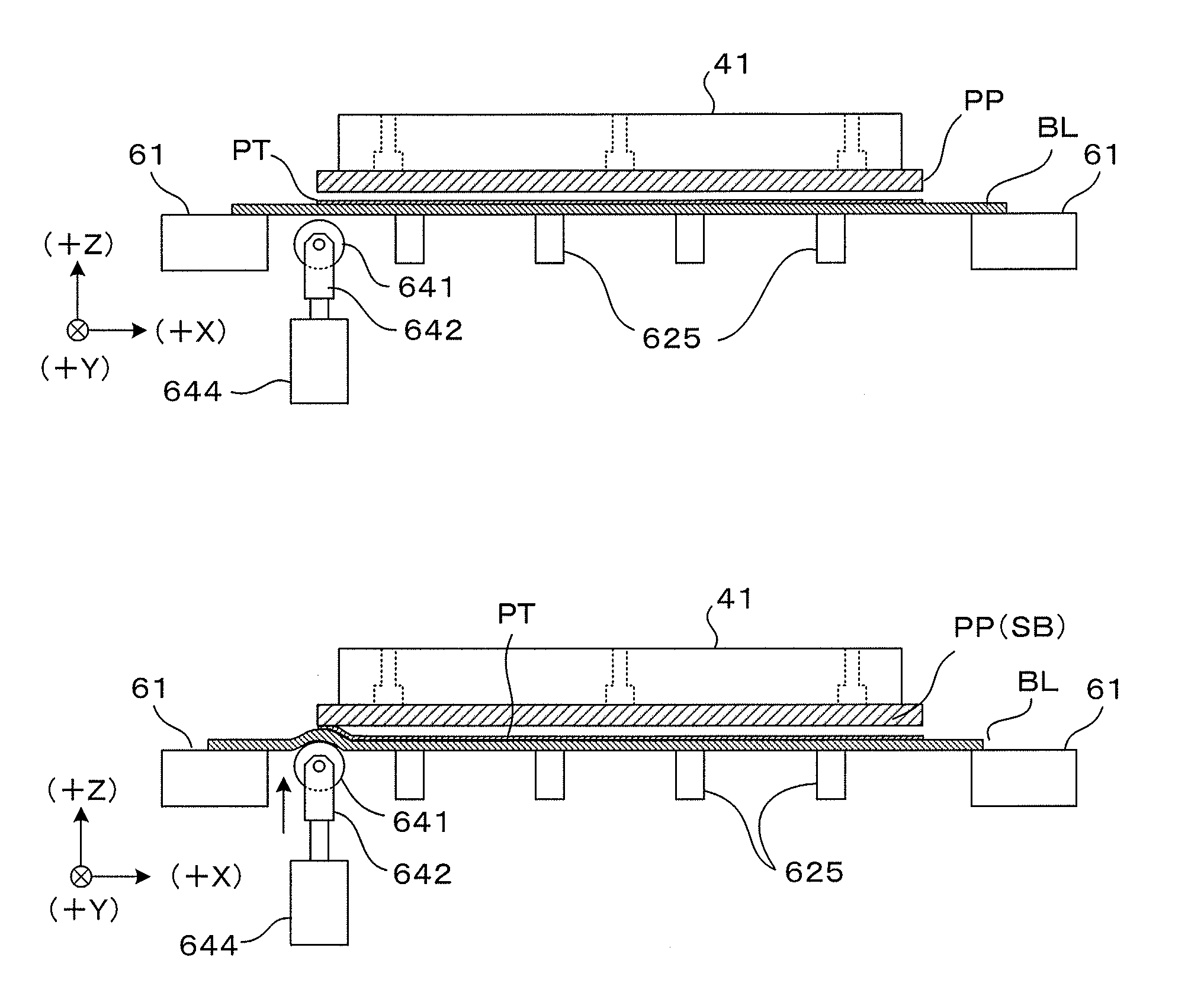
[0138]FIG. 17 is a view which shows a main part of the second embodiment of the pattern forming apparatus according to this invention. More...
third embodiment
[0170]Next, a third embodiment of the pattern forming apparatus according to this invention is described. In the pattern forming apparatus of the third embodiment, the structure of a lower stage block partly differs from that of the pattern forming apparatus 1 of the first embodiment described above. On the other hand, other components in the first embodiment, i.e. the main frame 2, the upper stage block 4, the control unit 7 and the like can be basically applied as a main frame, an upper stage block, a control unit and the like in the third embodiment as they are. Accordingly, the following description is centered on points of difference from the first embodiment, particularly the structure and operation of the lower stage block. Further, the same components as in the first embodiment are denoted by the same reference signs and not described.
[0171]FIG. 21 is a view which shows a main part of the third embodiment of the pattern forming apparatus according to this invention. More spe...
PUM
| Property | Measurement | Unit |
|---|---|---|
| Size | aaaaa | aaaaa |
| Area | aaaaa | aaaaa |
Abstract
Description
Claims
Application Information
 - R&D
- Intellectual Property
- Life Sciences
- Materials
- Tech Scout
- Unparalleled Data Quality
- Higher Quality Content
- 60% Fewer Hallucinations
Browse by: Latest US Patents, China's latest patents, Technical Efficacy Thesaurus, Application Domain, Technology Topic, Popular Technical Reports.
© 2025 PatSnap. All rights reserved.Legal|Privacy policy|Modern Slavery Act Transparency Statement|Sitemap|About US| Contact US: help@patsnap.com


